• This site contains eBay affiliate links for which Sea-Doo Forum may be compensated.

Challenger 4tec Upgrade

Status
Not open for further replies.
Worked on it quite a bit. Got the sides and bottom cut, bent and mostly welded.
235.jpg

236.jpg

237.jpg

238.jpg
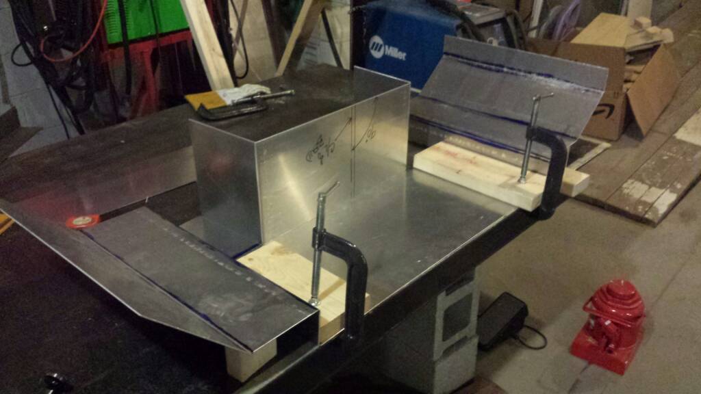
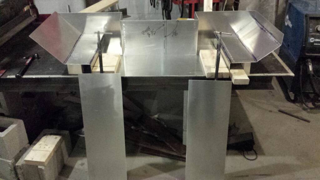
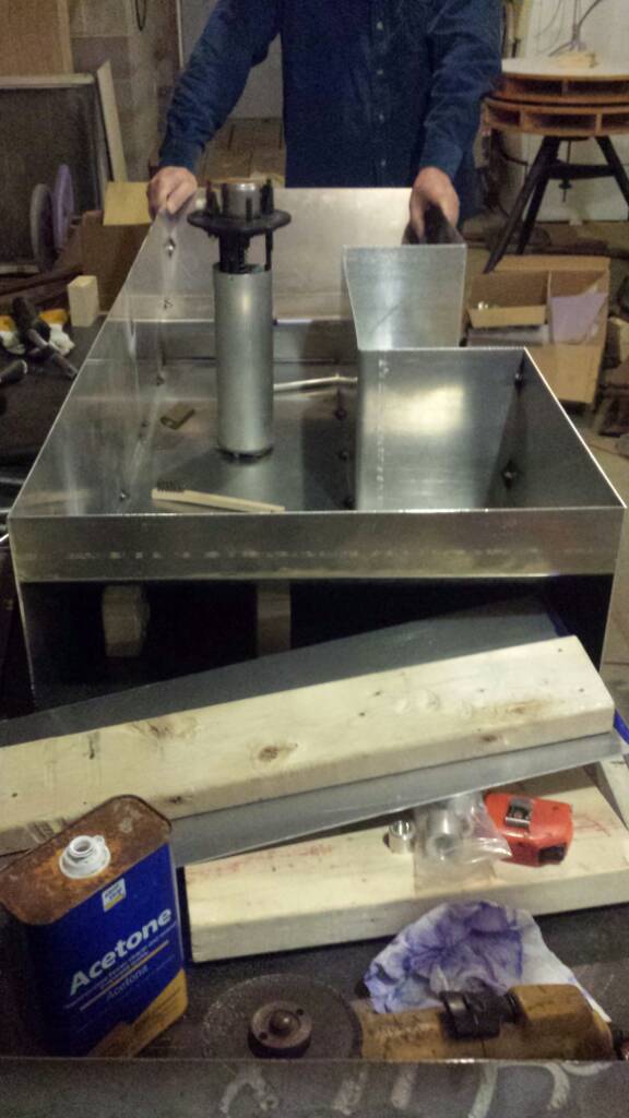
Decided to not cut out the complex shapes of the front and rear walls. Instead I just cut to size a rectangle and welded it on. I'll go back with a router and trim the edges flush before welding the outside. I will need to create a cylinder to recess the fuel pump into the tank so it doesn't stick up and interfere with the low fuel tank ceiling. Also need to cut bend and weld on the troth an the bottom center of the tank and weld in baffles. I'd say on about half way done with this baby!
239.jpg


Sent from my SCH-I545 using Tapatalk
 
Last edited by a moderator:
Oh Yea? How come? I probably have another weekend left to finish this one up. Welded all the seams on both sides. The welds aren't the prettiest, but they're solid!


Sent from my SCH-I545 using Tapatalk
 
317.jpg

318.jpg

Had to put a temporary top and troth to make doubly sure it would actually go in. That was before all the welding really commenced.

Sent from my SCH-I545 using Tapatalk
 
So I've pretty much got the fuel tank figured out. This weekend I ought to have it done. Can't wait to see how much it'll hold. The 3d model estimates 35 gallons, but in reality, it's a bit larger :D 
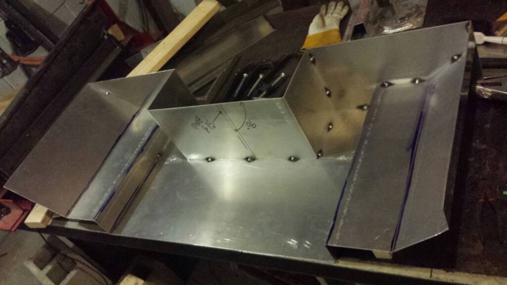
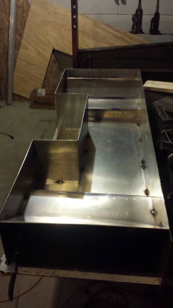
I plan to install an aluminum tube that goes to the very bottom welded to a 3/8 NPT bung. This would come in handy for draining, cleaning or removing water from the tank. I'm going to drill out a circular access hatch under the middle seat so I can get to the fuel pump if it ever goes out. Going to cover it up with a thin sheet of aluminum screwed into the glass. Since this tank is taller than the original, it's going to be even harder to bolt and unbolt those seats. I'm thinking of fabricating some sort of hook/catch system, at least to replace those two front bolts. Those were a nightmare, not to mention the bolts are like 2" longer than they need to be :bs:

It's driving me crazy not being able to work on it on the weekdays. I'm stuck on site 2.5 hours away from home. I really want to be making progress on it, but instead all I can do is plan and day dream about it. After I finish the tank, I want to reinforce the ride plate.
Ride Plate.jpg
Right now, it just bolts up with those two front bolts. I see lots of guys attaching them to their pump on the big v8 jet boats. Despite the fact that I have the aluminum pump, I don't want to attach anything to it. That would put unnecessary stress on the pump and the graft. Instead, I want to make fins to attach it to the transom just to the side of the graft. Something like this:
Ride Plate reinforcement 2.jpg
 

Attachments

  • Ride Plate reinforcement 2.jpg
    Ride Plate reinforcement 2.jpg
    1.3 MB · Views: 89
  • Ride Plate reinforcement 2.jpg
    Ride Plate reinforcement 2.jpg
    1.3 MB · Views: 91
Last edited by a moderator:
So I didn't finish the tank this weekend. First, I cut and welded in some baffles:
uploadfromtaptalk1454343067354.jpguploadfromtaptalk1454343084058.jpg
I went and welded over the tacks you see in the picture. Those baffles are not going anywhere. Next I measured, cut, bent and welded in place the siphon tube. It will pull from the very bottom rear of the tank. Next I cut holes for the baffles and tube in the top sheet.
uploadfromtaptalk1454343213962.jpg
Up to this point, everything fit beautifully. Then it came time to add the pump mount. I carefully measured and marked where it needed to go and started welding it on. When I was finished, I realized the sheet warped considerably! I immediately stopped and let everything cool down. I hammered some of it back into shape, but more measures will need to be taken to get it on straight. Here is me trying to prevent further warpage while welding the threaded mounting plate to the recess cylinder.
uploadfromtaptalk1454343593502.jpg
It worked, no more additional warpage occurred, but that's where I ran out of time. I'll get back to it Saturday and finish getting to top on and get it into boat [emoji1]


Sent from my SCH-I545 using Tapatalk
 
Just finalized my bilge pump plan and ordered the additional goodies. I'm going to have two pumps. The first will be my old, but recently replaced 500gph Rule on a new float switch. This will be my automatic every-day pump to siphon out whatever leaks past the carbon seal and any other normal water intrusion. The second will be my OH SHIT pump: a Johnson 2200GPH monster.
1.jpg

It draws like 7-10 amps, so I'm probably going to have to put it on a relay. Not sure that little switch on the console is rated for that much juice, besides, on these Challengers, there was some sort of control computer that a bunch of wires went to/came out of. I haven't taken the time to go through the huge wire loom I pulled out of the hull, but I bet there are some relays in there to prevent fires. Anyway, the bilge will be on the stock 3-position switch: Off, Auto (single pump) and Emergency (both pumps). I also might drill another hole in the deck or maybe in the ski locker compartment to let water out. I realized that the only way water can get out of the passenger area is either through the drain pipe under the driver seat, or via the ski locker. Well, in the ski locker, that hole is only about 3/4-1" wide. That 2200 pump would need more than that to keep it chugging, not to mention the additional 500 one. This is probably overkill, but it only takes one freak occurrence to make for a really bad day.
 
Last edited by a moderator:
Made a ton of progress on the tank but still am not 100% done.
56.jpg

Here is a shot of the baffles and pick up tube. It goes down to the bottom of that troth.
57.jpg

Next I cut the slots and holes in the top and welded that on. Then I trimmed the excess and ground off the burred edge.
58.jpg

There it is nearly complete. Started testing for pin hole leaks. Use a bicycle pump attached to the original fuel pump vent and a bunch of very soapy water. Found like 22 tiny pin holes the first go round and realized something important. When testing for leaks you must
1. Mark the leak.
2. Number the leak
3. Track the numbers on a spreadsheet or something.
Took me three times to figure that out and find all the leaks. Also on 3rd go realized that you need to add quite a bit of pressure to find the really tiny pore leaks. Idk how many psi the pump is getting to, but I found a bunch more leaks when the top developed a slight bulge. After I get all the leaks welded up, I will strap it to a trailer, fill it up and go drive around bumpy roads to simulate water conditions. I want to make sure nothing pops or cracks right away or I'll be using my new bilge pump to bail out fuel
59.jpg


Sent from my SCH-I545 using Tapatalk
 
Finished the ride plate braces tonight. Just need to drill the holes to mount them.
95.jpg

Exhaust system is next!
 
So I had an epiphany today: Why cross the exhaust over the pump tunnel? I can keep it all on the same side and use the original exhaust hole! The only downside is I might have to move the water box outlet to the other side. Exhaust will come out of the waterbox, go up and bend 180deg and enter the resonator. Then straight shot out of the transom. The height of the tallest point should be the same as in the original setup and should prevent back flooding. The aluminum bent tubes are really cheap on ebay. I hope that resonator has enough room to fit this plan.
I ended up buying the 2008+ exhaust system (the one without the J-pipe) but it seems even longer than the earlier setup. I'll have to shorten the waterbox considerably to fit.

The boat is coming home this weekend to my warm and well lit garage. My dad's doesn't have heat and it's going to be in the 20's this weekend. Can't wait for nice weather again! Man, once the exhaust is in, I can jerry rig the rest of it for a little water test.
 
Looking today at the exhaust setup, I will not be able to use the new style exhaust system. I would literally have to cut the waterbox in half (or maybe 1/3) because I cannot change the angle at which exhaust enters the WB. With the J-pipe, I can rotate the waterbox some, and not cut as much of it off. Also, I have already made the fiberglass mounts and don't have to cut/redo anything. Today I welded up my shorty WB and cut some hose. I hope I can use my old seadoo XP outlet initially. Eventually though, I'm going to get an aluminum bent pipe and have the pipe stick in the water while I'm idling/going slow. I don't want to hear the sound of the exhaust drone when I'm trying to just cruise slow and chill.

I have the fuel tank all welded up, but it's not quite ready to be dropped in. I'm waiting on my final addition. I'm going to smear all the welds with PR-1440 compound. It's an aviation fuel tank sealant. I really want to take 0 chances with gasoline and in case any pinholes ever decide to open up, this stuff will block them. Most of the fabrication is done for now. Lots of assembly now. The boat is finally back in my garage!
 
You need to seal the tank from the inside. Google "gas tank kreem", people have been using it for ever. I've personally used it on an motorcycle tank that had a good amount of rust and it worked. It was a bike my neighbor bought to flip. The guy is still using it and that was about 4 years ago.
 
No can do now, it's all welded up. I might be able to get to the troth and the central areas, but the baffles will keep me out of most of it.
 
You pour it in, cap it and rotate the tank around. It makes a membrane, it's not a paint on sealant.
 
Oh ya, I read about that. Tank sloshing compound. Read bad things about additives in the fuel. Methanol particularly eats away at it
 
Mounted the ride plate braces today. They came out rather nice I think.
116.jpg

117.jpg

Now I have a question for all you 4tec owners: the original resonator was different, so how should this plastic resonator sit in the hull? What is the angle of that flat area?
118.jpg
My natural instinct is to angle it so water flows out, but it's design suggests that it sits flat.
 
So my challenge this weekend is to finish the exhaust. I have it mostly figured out, just need to create a mounting system for the resonator.
144.jpg
145.jpg
146.jpg

I want to make the main bracket removeable. It will bolt onto that base bar which will be rivited and sealed to the hull.
 
Doing a great job.

BUT.....


You may want to weld some round tube to the edges of the ride plate mounts. (Putting a bead on it) I would hate for someone to jump of the back, and cut them selves on the aluminum.


FYI... I almost did this to my Islandia 4 years ago. I wasn't sure if I wanted to resurrect the Mercury engine. BUT... if mine pop's again... I will be looking into it. So I'm very interested in the outcome.
 
Thanks doc. I thought about what you said about the rideplate, but upon further examination, I'm going to leave it alone. It actually doesn't protrude past the swim platform at all. I think the picture was a little deceiving.

Today I fished fabbing up the resonator support. 4 8mm bolts secure it to its base, which is glassed onto the hull.
162.jpg
163.jpg
164.jpg
165.jpg


Also I finished the design and welding of the heat exchanger and strainer mount. It's going to go behind the driver seat. There are two 6mm bolts from the old electrical box already sticking out for me to use. The bottom of the mounting plate will go into an aluminum tab pocket and just slide in. It'll be held on by a bunch of rivets and bear most of the weight.
166.jpg

I'm going to mount it so that the exchanger will drain on its own after every trip. I'm also going to mount a t fitting and drain valve on the lower j-pipe hose. Maybe one on the manifold too, but I'll have to see if it's necessary, as I believe that hose is the lowest point. The goal is to have a super easy winterizing procedure. I want to only have to remove the strainer bowl, and open a valve and be done with it. I use this boat too much in the winter and don't want to worry about it every time I take it out between Nov and march.
 
Damn, I just realized that I probably can't mount the heat exchanger that high above the motor. I believe the highest point has to be the coolant reservoir for proper circulation, and there is no more room to go any higher with my original plan... I will have to find a spot lower for it.
 
Im so following this build. Keep the pics coming if you need any hosted let me know :)
Thanks, will do. Glad to know someone out there is reading this :) if nothing else, it helps serve as a sort of log book for myself. It has come in handy to remind myself what I was thinking a year or two ago.
Not much progress last night. Finished gooping up my fuel tank welds with that pr1440. Man that stuff is thick at 55F. Smells like ass too, I had my breathing apparatus on as there is toluene used in the compound. I'll get pics once it's dry.
Mounted the exhaust resonator too. It's sitting firm now!
185.jpg
186.jpg
 
Cut my hoses to length and used the union fitting.
188.jpg
189.jpg
It fits perfectly, but will probably interfere with the storage bin. This will surely damage the sound insulation and possibly even cause vibrations. In that case I will have to modify the water box by cutting the outlet down and also removing that stupid resonator offshoot. I almost removed it last weekend but was tired of welding and didn't feel like pressure testing the muffler again.
 
Status
Not open for further replies.
Back
Top