-
This site contains eBay affiliate links for which Sea-Doo Forum may be compensated.
You are using an out of date browser. It may not display this or other websites correctly.
You should upgrade or use an alternative browser.
You should upgrade or use an alternative browser.
SeaDoo Speedometer sensor fix instructions
- Thread starter 69DartGT
- Start date
Would you have any interest in repairing these for profit?
Darrellnbay
New Member
SS41 is $6.40ea, at Mouser Electronics I just ordered all 3 parts under $10 shipping cost more was $20Thanks for the reply. Never did a voltage check. I did check the price of a sensor and decided it was working well enoughLooking at the cost of an SS41 and a diode (my time is free since I am retired) and your excellent instructions , it is not working well enough now.
69DartGT
Member
I just looked and the SS41 was $4.32, did you order the correct one? You need part # 785-SS41.SS41 is $6.40ea, at Mouser Electronics I just ordered all 3 parts under $10 shipping cost more was $20
Darrellnbay
New Member
Can $ exchangeI just looked and the SS41 was $4.32, did you order the correct one? You need part # 785-SS41.
BrianMoore
Member
I bought 3 Honeywell SS41's for $10 shipped to my door off EBAY. I would rather get a name brand since they may have better quality control. I am waiting to see if the picture and description in the ad were true. I also bought 3 no name Zener Diodes for $8 same way. I could have driven for an hour round trip and picked up the diodes locally for a quarter each. Didn't see the SS41's listed being in stock at the local supplier, but they may have had them. Traffic is terrible around here, Seattle area, so I'll pay a few bucks more just to not have to deal with it. Waiting for the parts to get here also has allowed the weather to warm so I don't have to lay in water and ice to remove the pick up.
69DartGT
Member
That is the exact SS41 I used, just make sure the diode has the same specs as the one I have listed.I bought 3 Honeywell SS41's for $10 shipped to my door off EBAY. I would rather get a name brand since they may have better quality control. I am waiting to see if the picture and description in the ad were true. I also bought 3 no name Zener Diodes for $8 same way. I could have driven for an hour round trip and picked up the diodes locally for a quarter each. Didn't see the SS41's listed being in stock at the local supplier, but they may have had them. Traffic is terrible around here, Seattle area, so I'll pay a few bucks more just to not have to deal with it. Waiting for the parts to get here also has allowed the weather to warm so I don't have to lay in water and ice to remove the pick up.
BrianMoore
Member
The ones I ordered won't work, correct?
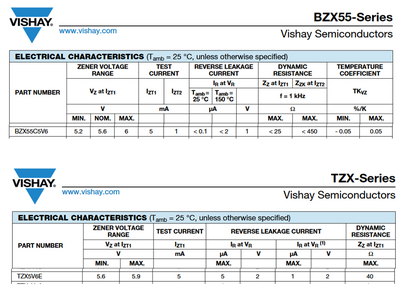
I see you have worked with nimrods before. I just found something that said 5.6V 1/2 watt. I didn't pay attention to the part number. I see that wasn't enough. I got a BZX55 series and not the TZX series and they are not the same. Oh well, live and learn. I'll order the right one this time.

I see you have worked with nimrods before. I just found something that said 5.6V 1/2 watt. I didn't pay attention to the part number. I see that wasn't enough. I got a BZX55 series and not the TZX series and they are not the same. Oh well, live and learn. I'll order the right one this time.

BrianMoore
Member
Progress report on fixing my 97 GTI two-wire pickup. My first mistake was not buying a 1K resistor to test the pickup before I dug into it. I wish I had data to reference and I did end up buying a resistor to check my work anyway. 30 cents well spent.
I bought the components before I removed the pickup. That was another mistake. I was lucky and only one insert spun when I removed it. I was able to get that screw out by putting upward pressure on the rest of the pickup and spinning the screw with an impact driver. It could have gone badly if multiple inserts had spun I imagine. The rest was easy. I had a pin extractor tool and a 19mm and 22mm crowsfoot to take the bulkhead wire feedthrough apart.
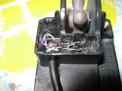
Removing the potting wasn’t fun. I did some shallow drilling to give it some flex. I loosened the edges with an exacto knife and pried it out in a couple of big chunks with a screwdriver. I was able to get the SS41 and Zener out in one chunk. I found the chip is located with a molded in clip. Also the original diode was a 1N752A. That cross references to a Vishay BZX55C5V6 or NTE NTE5011A. The 1N752A body doesn’t look like glass like the others.

Boy those components are tiny and a pain to solder. I used the TZX diode I bought second time around. I checked my work with a meter before I installed them into the pickup. I reassembled the new components into the pickup and did a test with a battery and a 1K resistor of the final assembly before potting. I got 5.66V to 8.16V. Reading other posts I thought the high side was low. Sure wish I had tested before disassembly.

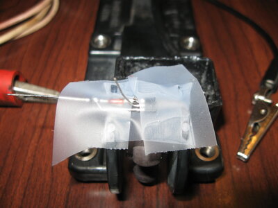
But I also had 2 more SS41s and some BZX55 diodes I had bought previously. I assembled a set of those and taped it to the pickup outside the cavity and tested those. I got 5.52V to 7.96V. Just because a reading has a bunch of decimal places doesn’t say anything about the significance of the hundredths of a volt. Both sets were showing around a 2.5V difference in rise so that make me feel better.

I used super glue around the threaded inserts in the body because all had stress cracks in the plastic. It is thin enough that it wicked a lot in due to capillary action. I ran a tap though all of the inserts and none of them spun. I still have to pot the electronics. I was going to hot glue it but I am a little afraid of the temperature and the electronics. I also bought some E6000. If it is what I am thinking of, I have been looking for that stuff for a long time. I had a tube of some adhesive under a different brand name and loved it. I haven’t been able to find the same stuff for decades.
I bought the components before I removed the pickup. That was another mistake. I was lucky and only one insert spun when I removed it. I was able to get that screw out by putting upward pressure on the rest of the pickup and spinning the screw with an impact driver. It could have gone badly if multiple inserts had spun I imagine. The rest was easy. I had a pin extractor tool and a 19mm and 22mm crowsfoot to take the bulkhead wire feedthrough apart.
Removing the potting wasn’t fun. I did some shallow drilling to give it some flex. I loosened the edges with an exacto knife and pried it out in a couple of big chunks with a screwdriver. I was able to get the SS41 and Zener out in one chunk. I found the chip is located with a molded in clip. Also the original diode was a 1N752A. That cross references to a Vishay BZX55C5V6 or NTE NTE5011A. The 1N752A body doesn’t look like glass like the others.

Boy those components are tiny and a pain to solder. I used the TZX diode I bought second time around. I checked my work with a meter before I installed them into the pickup. I reassembled the new components into the pickup and did a test with a battery and a 1K resistor of the final assembly before potting. I got 5.66V to 8.16V. Reading other posts I thought the high side was low. Sure wish I had tested before disassembly.

But I also had 2 more SS41s and some BZX55 diodes I had bought previously. I assembled a set of those and taped it to the pickup outside the cavity and tested those. I got 5.52V to 7.96V. Just because a reading has a bunch of decimal places doesn’t say anything about the significance of the hundredths of a volt. Both sets were showing around a 2.5V difference in rise so that make me feel better.

I used super glue around the threaded inserts in the body because all had stress cracks in the plastic. It is thin enough that it wicked a lot in due to capillary action. I ran a tap though all of the inserts and none of them spun. I still have to pot the electronics. I was going to hot glue it but I am a little afraid of the temperature and the electronics. I also bought some E6000. If it is what I am thinking of, I have been looking for that stuff for a long time. I had a tube of some adhesive under a different brand name and loved it. I haven’t been able to find the same stuff for decades.
69DartGT
Member
Hey Brian, looks great! Your readings look good to me, have you tried it on the ski yet to see if the speedo works? Also, if the
inserts break I have seen guys just use bolts with washers and nuts to bolt the pickup back on. It is almost impossible not to break a
couple when removing them.
inserts break I have seen guys just use bolts with washers and nuts to bolt the pickup back on. It is almost impossible not to break a
couple when removing them.
Last edited:
BrianMoore
Member
Ski is winterized so no operational test until spring. Until then I assume it is working better. I'll remember to post later if this project was a failure.
I used E6000 for potting. It is what I thought it was. But I also never filled such a large cavity. It shrinks a lot. I'll give the first fill a couple days to shrink more then top it off. If I were ever to do it again, I would fill half, let it cure and shrink, then add the second half.
I used E6000 for potting. It is what I thought it was. But I also never filled such a large cavity. It shrinks a lot. I'll give the first fill a couple days to shrink more then top it off. If I were ever to do it again, I would fill half, let it cure and shrink, then add the second half.
Darrellnbay
New Member
69DartGT
I was able to do some bench testing today, GTX1996 SEADOO Speed sensor give me voltage between 3.5vdc and 7.5vdc when spinning the paddle wheel and voltages in between faster slower. So I think that works OK. I also did a test using components same results. But I was not able to get the speedometer to work. Power applied gave me oil indicator and adding gnd turned indicator off. So that worked OK. Is there a circuit that would allow me to use a resistor pot where center lead would give me higher and lower voltages to have speedometer show speed based on voltages?
And possibility what voltages low/ hight could I apply to PU YL Input ?
Thanks
69DartGT
Member
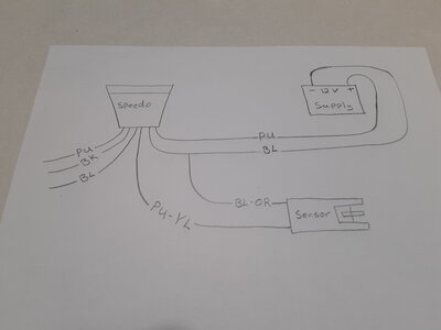
When I bench tested the speedometer I did not use the 1K resister from the 12V power supply to the PU wire of the speedometer like I illustrated above. I drew the resister in just to be on the safe side, try it without the resistor. When I did this I did it quickly, just to verify I could get the speedometer to move.69DartGT
I was able to do some bench testing today, GTX1996 SEADOO Speed sensor give me voltage between 3.5vdc and 7.5vdc when spinning the paddle wheel and voltages in between faster slower. So I think that works OK. I also did a test using components same results. But I was not able to get the speedometer to work. Power applied gave me oil indicator and adding gnd turned indicator off. So that worked OK. Is there a circuit that would allow me to use a resistor pot where center lead would give me higher and lower voltages to have speedometer show speed based on voltages?
And possibility what voltages low/ hight could I apply to PU YL Input ?
Thanks
Darrellnbay
New Member
So apply power to speedometer +12v, to 1K ohm R to PU, BK -12v, OIL LIGHT comes on, add -12v to BL light goes off, so apply 12+ to PU YL just to see is needle moves?When I bench tested the speedometer I did not use the 1K resister from the 12V power supply to the PU wire of the speedometer like I illustrated above. I drew the resister in just to be on the safe side, try it without the resistor. When I did this I did it quickly, just to verify I could get the speedometer to move.
Should I leave the 1 K ohm R in to feed power to the speedometer PU, but go directly back to battery to do the quick test +12v to PU YL?
Last edited:
Darrellnbay
New Member
Sounds great. Thank you for your assistance
Darrellnbay
New Member
Very much understand. And thanks for your assistance.
69DartGT
Member
Ok, so I tried bench testing a speedometer with the 1K resistor in the circuit and it did not move. So I took the resistor out and the speedometer needle moved. I also checked the voltage of the PU wire feeding the speedometer on the ski and it was 11.5V. So using 12V to the speedometer PU wire that you are bench testing should not hurt it, but I did it quickly just make sure the speedometer needle moved to be on the safe side.Very much understand. And thanks for your assistance.
So use the Speedometer diagram in post #26, but leave out the 1K resistor and see what happens.
Darrellnbay
New Member
I will give that a try. The 1k would have 12mA in the circuit. Seems not enough to activate the circuit. I will give this a go but possibly use 100 ohm then lower just to see. I'll let you know. Thanks
69DartGT
Member
Sounds good. I hope it works for you. I revised the drawing for bench testing the speedometer. I did it this way again tonight and was able to run the speedometer up all the way with compressed air.I will give that a try. The 1k would have 12mA in the circuit. Seems not enough to activate the circuit. I will give this a go but possibly use 100 ohm then lower just to see. I'll let you know. Thanks
Last edited:
Darrellnbay
New Member
I was able to test the speedometer just by it's self.
12+ to PU
12- TO BK
This lights the LED oil low indicator
Applying 12- gnd to the BL turns indicator off
Giving PU YL a pluse tap tap activated the speed pushing it upwards of 40 + MPH
No inserted R values into the circuit works.
So the speed sensor controls the amount of 12- gnd voltage coming out on the PU YL to the speedometer more gnd it sees the faster we go.
BK OR to 12- gnd is the feed into the sensor.
I did not get the sensor I have to work with the speedometer SO looks like I'll build the circuit using the components.
Is there any chance the paddle wheel magnetic pull would fail to activate the mag switch giving it no frequency Cycle?
69DartGT
Member
I wouldn't think the magnets would fail, but I have seen weirder things in life. That is odd that your sensor is not operating the speedo since the voltage readings looked good. I am beginning to think you understand this way more than I do. lolI was able to test the speedometer just by it's self.
12+ to PU
12- TO BK
This lights the LED oil low indicator
Applying 12- gnd to the BL turns indicator off
Giving PU YL a pluse tap tap activated the speed pushing it upwards of 40 + MPH
No inserted R values into the circuit works.
So the speed sensor controls the amount of 12- gnd voltage coming out on the PU YL to the speedometer more gnd it sees the faster we go.
BK OR to 12- gnd is the feed into the sensor.
I did not get the sensor I have to work with the speedometer SO looks like I'll build the circuit using the components.
Is there any chance the paddle wheel magnetic pull would fail to activate the mag switch giving it no frequency Cycle?
Similar threads
- Replies
- 3
- Views
- 157
- Replies
- 6
- Views
- 926
- Replies
- 2
- Views
- 486
- Replies
- 3
- Views
- 859
Share:


