


There have been a few members riding skis who have asked how to get into the gage compartment. One of our members, Neal B has been working on his 1996 GTX to get all his gages out. He sent the pix to me due to the 5 picture limitation that members have. If you have any questions about this post, please contact Neal B. I’m sure he’ll be happy to help you out.
The only thing I might add is that, he’s looking to separate the clear plastic face plate. You cannot do this. The face plates are a sealed with an inert gas, like Argon, to keep them from fogging. If you break this seal, you will have to get Argon or Nitrogen to reseal these plates back up.
Seadoosnipe
1996 GTX Instrument Gauge cluster removal by Neal B:
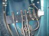
Open front storage cover and remove 6 pan head screws/bolts holding “storage cover lower” in place. There are five harnesses here. I put same color wire ties on either side of connector plugs incase I had to separate the plugs. The separating was not necessary but the plugs did have to be removed from their slide in holders for movement later.
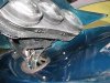
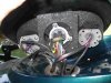
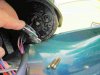
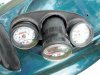
Above the slots are two bolts that have to be removed to loosen the deflector that holds the instrument cluster (See Pix 1). The instrument cluster is still attached to the deflector. The two bolt (previous two bolts) holes are visible on the bottom of the cluster. (See Pix 2) In this photo you can see the gauges in the three hole dash board, behind this, a three hole gauge foam, and further down, on only the center gauge, is a square gauge foam piece (See Pix 3).
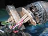
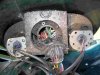
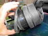
To remove the instrument gauge cluster from the deflector (See Pix 4) the foam’s have to be removed. I used a razor and cut the upper edge of the square foam (to avoid an accidental wire cut) and the bottom of each of the three holes in the three hole gauge foam. Pull the foam gently towards the rear and gently open the foam to slide the wires through. The parts book calls this foam but it has more of a cork consistency than foam so be careful, it breaks easily but gorilla glue will put it back together again (yep, learned the hard way). If the foam comes off you will not have to remove the separate metal disks that hold the wires and grommet seals into the back of each gauge. I did to get better access to the wires (See Pix 5 and 6).
There are three to five screws holding the plates on. Inside the plates are three 2+ inch brass screws. I think these have to be removed to get the clear plastic lens off the instrument housing but wouldn’t swear to it as I haven’t been able to separate the clear lens from the instrument yet. (See Pix 6 and 7).
Once the foam is removed you can see the two 5.5mm hex pan head screws holding the instrument deck to the deflector (See Pix 4). Remove the two screws See Pix 8). There is a rubber grommet holding the instrument gauges in the dashboard. The gauges will turn inside the grommets and have to be pulled forward to expose the grommet. Pry the rubber grommet out of the hole, inside and fold over to remove them from their position around the instrument deck hole (See Pix 9). Slide the grommet back over the back side of the instrument.
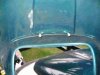
To remove the gauge from the dashboard, move the bottom through the hole first, pull instrument down and slide the top through the hole. (See Pix 10 and 11). With all three gauges out, they are individually accessible if the metal plates are removed. The wires go to pins inside the gauges.
Now, someone tell me how to separate the clear plastic lens from the rest of the gauge!
Neal
The only thing I might add is that, he’s looking to separate the clear plastic face plate. You cannot do this. The face plates are a sealed with an inert gas, like Argon, to keep them from fogging. If you break this seal, you will have to get Argon or Nitrogen to reseal these plates back up.
Seadoosnipe
1996 GTX Instrument Gauge cluster removal by Neal B:
Open front storage cover and remove 6 pan head screws/bolts holding “storage cover lower” in place. There are five harnesses here. I put same color wire ties on either side of connector plugs incase I had to separate the plugs. The separating was not necessary but the plugs did have to be removed from their slide in holders for movement later.
Above the slots are two bolts that have to be removed to loosen the deflector that holds the instrument cluster (See Pix 1). The instrument cluster is still attached to the deflector. The two bolt (previous two bolts) holes are visible on the bottom of the cluster. (See Pix 2) In this photo you can see the gauges in the three hole dash board, behind this, a three hole gauge foam, and further down, on only the center gauge, is a square gauge foam piece (See Pix 3).
To remove the instrument gauge cluster from the deflector (See Pix 4) the foam’s have to be removed. I used a razor and cut the upper edge of the square foam (to avoid an accidental wire cut) and the bottom of each of the three holes in the three hole gauge foam. Pull the foam gently towards the rear and gently open the foam to slide the wires through. The parts book calls this foam but it has more of a cork consistency than foam so be careful, it breaks easily but gorilla glue will put it back together again (yep, learned the hard way). If the foam comes off you will not have to remove the separate metal disks that hold the wires and grommet seals into the back of each gauge. I did to get better access to the wires (See Pix 5 and 6).
There are three to five screws holding the plates on. Inside the plates are three 2+ inch brass screws. I think these have to be removed to get the clear plastic lens off the instrument housing but wouldn’t swear to it as I haven’t been able to separate the clear lens from the instrument yet. (See Pix 6 and 7).
Once the foam is removed you can see the two 5.5mm hex pan head screws holding the instrument deck to the deflector (See Pix 4). Remove the two screws See Pix 8). There is a rubber grommet holding the instrument gauges in the dashboard. The gauges will turn inside the grommets and have to be pulled forward to expose the grommet. Pry the rubber grommet out of the hole, inside and fold over to remove them from their position around the instrument deck hole (See Pix 9). Slide the grommet back over the back side of the instrument.
To remove the gauge from the dashboard, move the bottom through the hole first, pull instrument down and slide the top through the hole. (See Pix 10 and 11). With all three gauges out, they are individually accessible if the metal plates are removed. The wires go to pins inside the gauges.
Now, someone tell me how to separate the clear plastic lens from the rest of the gauge!
Neal
Attachments
-
 Pix 1.jpg178.3 KB · Views: 210
 -
 Pix 2.jpg170.9 KB · Views: 179
 -
 Pix 3.jpg175.4 KB · Views: 162
 -
 Pix 4.jpg379.3 KB · Views: 146
 -
 Pix 5.jpg352.1 KB · Views: 146
 -
 Pix 6.jpg648.9 KB · Views: 135
 -
 Pix 7.jpg413.7 KB · Views: 127
 -
 Pix 8.jpg120.9 KB · Views: 127
 -
 pix 9.jpg354.6 KB · Views: 167
 -
 Pix 10.jpg283.2 KB · Views: 149
 -
![F7_Instrumet_dashboard_1_back[1].jpg](/data/attachments/0/870-11aa9c2fb285607cd70339da3a32b1f1.jpg?hash=EaqcL7KFYH) F7_Instrumet_dashboard_1_back[1].jpg153.1 KB · Views: 144
F7_Instrumet_dashboard_1_back[1].jpg153.1 KB · Views: 144 -
![F7a_Infometer_ctr_guage_back_1[1].jpg](/data/attachments/0/871-b72351ba4e5fdd31f34f3b4a193303cf.jpg?hash=tyNRuk5f3T) F7a_Infometer_ctr_guage_back_1[1].jpg162.4 KB · Views: 110
F7a_Infometer_ctr_guage_back_1[1].jpg162.4 KB · Views: 110 -
![F7b_Infometer_ctr_guage_back_2[1].jpg](/data/attachments/0/872-83ac5f43e964b7035fe579282f607167.jpg?hash=g6xfQ-lktw) F7b_Infometer_ctr_guage_back_2[1].jpg389.9 KB · Views: 106
F7b_Infometer_ctr_guage_back_2[1].jpg389.9 KB · Views: 106 -
![F11_Instrumet_dashboard_5[1].jpg](/data/attachments/0/873-0edcd8efc56cc24118c4ca7195946477.jpg?hash=DtzY78Vswk) F11_Instrumet_dashboard_5[1].jpg194.6 KB · Views: 110
F11_Instrumet_dashboard_5[1].jpg194.6 KB · Views: 110