• This site contains eBay affiliate links for which Sea-Doo Forum may be compensated.

Motor reving but i go nowhere

Status
Not open for further replies.
Without the bumper, I have seen shafts spin as they are not in the correct alignment in regards to depth.


Sent from my iPhone using Tapatalk
 
Did not find a bumper in there....BUT I did fish out 2 small washers covered in grease. Im going to take off the allen head bolts and see if its "stuck" in there.
How hard to align motor? I never ever tried it or know anyone who has attempted it
 
Remember this is a custom application. Not your normal oem bombardier driveline and engine package. Adjustments are going to be different since you have a different engine etc. Let's get some more detailed pictures up of the boat, driveline, engine, couplings etc.

Plus we want to see more about how this was constructed and if it is an efficient combo/swap.

Rob
 
Last edited by a moderator:
I am soooo lost now. OK>>>>here's the scoop. All the above photos were taken AFTER I had the complete pump assembly off. That might have let the drive shaft hang down a hair causing the "not matching" up front by pto.
Im going to reassemble the WHOLE thing in the am and see what it looks like. In my photos of the motor before I started wrenching on it...it looks good. Sorry for all the hassle....
Thoughts??
Pic of motor before taking off pump.....
 

Attachments

  • motor notes.jpg
    motor notes.jpg
    932.2 KB · Views: 39
Remember this is a custom application. Not your normal oem bombardier driveline and engine package. Adjustments are going to be different since you have a different engine etc. Let's get some more detailed pictures up of the boat, driveline, engine, couplings etc.

Plus we want to see more about how this was constructed and if it is an efficient combo/swap.

Rob
here are some pics
 

Attachments

  • 0108.jpg
    0108.jpg
    112.4 KB · Views: 35
  • 00werwerwer9.jpg
    00werwerwer9.jpg
    385.3 KB · Views: 38
Remember this is a custom application. Not your normal oem bombardier driveline and engine package. Adjustments are going to be different since you have a different engine etc. Let's get some more detailed pictures up of the boat, driveline, engine, couplings etc.

Plus we want to see more about how this was constructed and if it is an efficient combo/swap.

Rob


I'll consider the PTO and back OEM, so bumpers, end play and alignment still should work like the original set-up.


Did not find a bumper in there....BUT I did fish out 2 small washers covered in grease. Im going to take off the allen head bolts and see if its "stuck" in there.
How hard to align motor? I never ever tried it or know anyone who has attempted it

I'll assume they used the washers like shims instead of the bumper. If everything lines up, to quickly add more tension to the boot/carbon seal you can loosen the rear hose clamp and push the boot towards the PTO and put a cable tie around the thru hull fitting. (See yellow cable tie in pic) Thanks Manolocross for the pic


70.jpg
 
I'll consider the PTO and back OEM, so bumpers, end play and alignment still should work like the original set-up.


I'll assume they used the washers like shims instead of the bumper. If everything lines up, to quickly add more tension to the boot/carbon seal you can loosen the rear hose clamp and push the boot towards the PTO and put a cable tie around the thru hull fitting. (See yellow cable tie in pic) Thanks Manolocross for the pic


70.jpg

We could but have to remember this is a custom application and the former owner/builder may have done some modifications to make it work in other areas too. IE washers instead of rubber bumpers. Just have to take all of that into consideration is what I'm pointing out.

Rob

Crazy difficulty replying to threads ugh.
 
Last edited by a moderator:
attachment.php


Sent from my SGH-T889 using Tapatalk
 

Attachments

  • uploadfromtaptalk1428121241862.jpg
    uploadfromtaptalk1428121241862.jpg
    78 KB · Views: 99
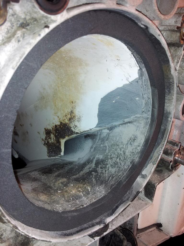
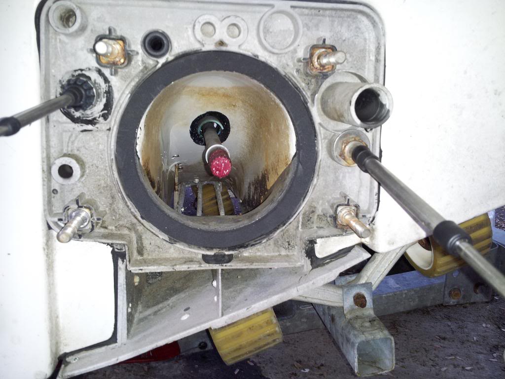
After a good nights sleep here's the plan. We're otta here for Easter so I'll get back at it on Monday. Going to take off intake grate and ride plate, clean it all up and reseal. Rebuild complete driveline, pump and clean up the current impeller. Permatex Black EVERYTHING smooth and tight. NO LEAKS. Back to water to see what happens.
Dremmel tool for the impeller edges to make them straight??? Not looking to take off alot of material but just even all edges out...that OK?
 
Update....spoke to Glen at SkatTrak. I need a bearing carrier instead of carbon seal. Ordered! New wear ring. Ordered! Once I remove impeller and tell him the number on it...he is going to ship me a prop and we go from there. That's all folks till parts get here. I will be wax on wax off. Thanks again for all the assistance!!
 
See anything that doesn't look right or something I need to fill, ect? Thanks in advance
 

Attachments

  • Pump inside.jpg
    Pump inside.jpg
    730.7 KB · Views: 22
  • pump outsdie.jpg
    pump outsdie.jpg
    594 KB · Views: 23
If it were me, I would remove the blue shaft protector. If you remove the bellow from the inside you will see teh tangs that hold it in place. There is also silicone or epoxy that holds it in too. It's supposed to aid in removal of a sucked up ski rope. Once you wrap a rope around it, it's trashed. I removed mine after someone sucked up a ski rope. I was not driving, so I can't blame myself for that one. The part where the wear ring sits against need a neoprene seal for sure. That will also help stop cavitation, the pump will push water past the wear ring seal against the plastic pump support. The neo is thick and totally seals the pump.


Here is a Challenger I did. The Neo seal is part# 293200024. You can see the shaft protector is gone in there too.

You can see how thick the seal is.

545.jpg


546.jpg
 
should i sand the inside of the pump cavity to make it uniform and smooth? I can fill the low spots with a peanut butter mixture of glass and sawdust, then sand. Can only wax the outside so much while I'm waiting on parts. Picked up a aux fan that I'm going to install under deck lid to help get rid of heat from eng. compartment. Possibly add a hood scoop as well.
 
Last edited by a moderator:
Got everything in the mail today....here's question. From the PTO, does that need a rubber boot? I didnt get one in the kit. The carrier bearing and long black hose with 4 clamps came...thats it. Ughh....going to put me back a few days if I need to order it.
 
Got it all back together.... BUT I forgot one piece. The (204120132 RING-RETAINING) Did not install it back on driveshaft. I left the shaft protector in place seeing that there was nothing wrong with it but the retaining ring...still in my "parts box" and not on the shaft. Any major issues?? Should be able to water test today, wind permitting.
 
You need the boot on the pto to shaft. You need to pump the pto with grease after you get the boots and clamps on. Without the grease the shaft can more forward into the pto and strip out the splines


Sent from my iPhone using Tapatalk
 
That retaining ring is blue plastic, correct? If so your fine.

Sent from my SGH-T889 using Tapatalk
 
UPDATE>>>> Hit the water and it moved!! Wouldn't really show thrust until 4000 rpm but at 8k it was on plane and MOVING! Cavitation problem solved with bearing carrier and no carbon "thing." BUT....after a quick water tour loaded back on trailer and noticed that the drive shaft moved out of the PTO a quarter inch backwards. Yes I put the bumpers in both side of shaft prior to install. Now if I had the boot on the PTO, I would have never known it moved cause wouldn't be able to see it. In photo you can see the splines of the shaft "outside" of the PTO. Is that normal? What would cause that? Pump housing is same as original along with drive shaft. Is it a big deal the way it sits now? In the custom fabrication I would assume that the PTO should have been "back" a quarter inch further....make sense. Big question...is it going to make it the way it is?
 

Attachments

  • Driveshaft moved back.jpg
    Driveshaft moved back.jpg
    932.5 KB · Views: 8
Sweet, it's probably normal distance out. But I can tell right off the bat the the pto is not properly aligned to the shaft. And you could prematurely wear out the splines on the shaft. It looks like there is more of a gap on the underside of the shaft. The grease will help take out the play in the lateral movement of the shaft, once the boot is on.

attachment.php


Sent from my SGH-T889 using Tapatalk
 

Attachments

  • uploadfromtaptalk1429037931818.jpg
    uploadfromtaptalk1429037931818.jpg
    115.3 KB · Views: 39
Last edited by a moderator:
Yep., needs aligned. And, if you are going to remove / loosen the muonts, might as well slide it all back about 1/4 inch to get all the spline into the PTO.

If all things were nice and straight, you could get a piece of steel, drill the right holes into it, put it between the PTO and the and the engine. Spline problem would be solved and you would not have to screw with the motor mounts.
 
Status
Not open for further replies.
Back
Top