Get a can of Deoxit. Radio Shack used to carry it and so does Guitar Center and Amazon. It is a contact cleaner that was originally used in the music industry but is awesome for all electronics. It actually removes corrosion unlike regular contact cleaner. Pretty amazing stuff.


-
This site contains eBay affiliate links for which Sea-Doo Forum may be compensated.
You are using an out of date browser. It may not display this or other websites correctly.
You should upgrade or use an alternative browser.
You should upgrade or use an alternative browser.
Another GTX Di
- Thread starter G&J
- Start date
- Status
- Not open for further replies.
Sportster-2001-951C-Stock
Well-Known Member
Yeah, you've got an open circuit somewhere, most likely on the stator side of the charging circuit. Don't forget, the rectifier must have a good ground to the battery negative terminal or it won't work.
I usually measure stator resistance of ~ 1 Ohm, 0.1 doesn't make sense to me but this is a DI and I've never measured a DI.
Water can get trapped inside the stator housing and of course will corrode the stator windings, that's pretty common.
Your ski should run fine with stator disconnected as long as battery voltage doesn't drop appreciably under 12V Too much voltage (from a battery charger being connected at some point, for instance) can damage the MPEM.
G&J
New Member
Hi
I can get this product in Australia... looks like it will do the trick!
http://www.jaycar.com.au/Service-Ai...Cleaner-&-Rejuvenator---Solution-Kit/p/NS1436
I can get this product in Australia... looks like it will do the trick!
http://www.jaycar.com.au/Service-Ai...Cleaner-&-Rejuvenator---Solution-Kit/p/NS1436
G&J
New Member
It also just occurred to me will I get an accurate AC voltage out of the "stator" with no load? That is the rectifier disconnected which I need to do as I don't have the special testing cable mentioned in the manual.
On that subject the 6 pin magneto harness adaptor - why six pins? My rectifier has a three pin (all yellow) plug to stator and 2 pin (black/red) to I assume the battery via the wiring harness.
edit: Could I not, using a clamp meter, measure the collective current out of the stator (three yellow wires) with everything plugged in?
Last edited by a moderator:
tkarvelis
Active Member
Yes you could use a clamp on amp meter to measure the current of each wire, You would not want to measure all three at once because it would not show which wire is broken, or intermittent.
The six pin adapter cable goes on the other end of the cable where it plugs into the coil. I am guessing Bombadier wanted you to measure closest to the coil.
If I remember you tested each wire yellow to yellow, and yellow to ground. The yellow to yellow were .1 -1.0 ohm, and yellow to ground was open.
I would bet you have an oxidized connection, and when you try to pull current (charge the battery) You are having the issue.
The other possibility is your fuel pump is pulling more current than the charger can supply.
G&J
New Member
Hi All
So far my new "hobby" is 90% working on repairing the SeaDoo and 10% of the time riding the Yamaha 2 stroke.
OK here we go.......
Pulled every connector I could find including MPEM AMP connectors and cleaned with Deoxit (good stuff!) reconnected everything and then:
1. Measured voltage at battery (tried old and new rectifiers) - voltage does not change sits around 12.5 - 12.6 V
2. Also to dot the I, put clamp ammeter on positive battery lead, idle/rev 1.5 to 2 amps never gets to the 5 amps stated in manual dynamic current test
Note: at idle info centre OK no error messages, if I rev the unit, red light comes on and 'warning' displayed (I assume low voltage causes this - don't have candoo to confirm might have to buy one (anyone got one they want to sell?))
3. Re measured resistance between yellow stator wires - all ok with range of .1 to 1 ohm. Also no short to earth
4. Don't have special magneto cable thingy so I put clamp ammeter on each individual yellow stator wire - all OK each wire shows similar amps that increases with revs
So my thoughts at this stage are I either have...
a. Received a faulty rectifier from OSD (if yes need to somehow confirm before shipping back to USA)
b. Wiring harness fault
c. The MPEM is faulty - looking at the wiring diagram am I correct in my assumption that the rectifier provides the "12v" to the MPEM which in turn provides charging voltage to battery? That is 3-25, RE-PU - if not how?
I would appreciate your thoughts / suggestions
G&J
New Member
Is there any static test that I can do with the OSD rectifier to confirm status before returning? I read somewhere you can test rectifier diodes, yellow to black?
Also... I was re-checking the earth to the rectifier resistance - zero - and couldn't remember if I had checked resistance between the red and black wires on the non rectifier side, tested the yellow (stator) multiple times.
What should the resistance reading be between the red/black wires with the rectifier disconnected - not the rectifier side, that is where the output from the rectifier goes? On the wiring diagram the red/black goes to 2-25 & 26 on the MPEM - so is resistance measurement pointless not knowing what's in the MPEM?
Last edited by a moderator:
jhjesse
Well-Known Member
Not sure about a test for the rectifier itself. 68ragtop will probably know, but for what it is worth I just finished rebuilding my 3rd di and started it for the first time today. It started doing the exact same thing your ski is doing. Fortunately I had my candoo pro connected at the time it threw a code/maintenance light came on. Both codes 10563 and 15001 say the likely culprit is the rectifier.
Sportster-2001-951C-Stock
Well-Known Member
Okay so let's assume the 3-phase AC is reaching the rectifier, then the output of the rectifier might not be reaching the battery (for whatever reason).
A couple ideas:
1) You should be able to measure battery voltage on the red output wire of the regulator while the engine is off. If not, the current which normally comes from the red wire of the regulator isn't going to push current into the battery due to no connection.
2) Also, these regulators wont operate if it's not grounded, make sure the ground of the regulator isn't open.
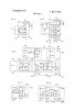
Further: I believe this is a full wave type regulator (See Figure 5), meaning it will have 6 rectifying devices internally (3 diodes & 3 SCR's. If it is this type, you will measure no DC voltage on the stator while the engine isn't running and you should be able to test 3 of the output rectifiers as diodes (flow current in one direction). The other three rectifying devices would be SCR's, which should measure open (not shorted). Using your ohmmeter.
If this is using a 1/2 wave type regulator (See figure 4), you will measure 12V on the stator while the engine isn't running (one phase of stator is connected to the battery + terminal).
Two drawings that might help, one is schematic of full wave R/R (figure 5) and other is 1/2 wave R/R (figure 4)... There are many ways of wiring a stator rectifier, but maybe one of these drawings will help you nail it... (probably the full wave figure 5 drawing).
Figure 6 is a shunt type regulator, which most likely doesn't apply.
Let me know if this makes sense for you!
A couple ideas:
1) You should be able to measure battery voltage on the red output wire of the regulator while the engine is off. If not, the current which normally comes from the red wire of the regulator isn't going to push current into the battery due to no connection.
2) Also, these regulators wont operate if it's not grounded, make sure the ground of the regulator isn't open.
Further: I believe this is a full wave type regulator (See Figure 5), meaning it will have 6 rectifying devices internally (3 diodes & 3 SCR's. If it is this type, you will measure no DC voltage on the stator while the engine isn't running and you should be able to test 3 of the output rectifiers as diodes (flow current in one direction). The other three rectifying devices would be SCR's, which should measure open (not shorted). Using your ohmmeter.
If this is using a 1/2 wave type regulator (See figure 4), you will measure 12V on the stator while the engine isn't running (one phase of stator is connected to the battery + terminal).
Two drawings that might help, one is schematic of full wave R/R (figure 5) and other is 1/2 wave R/R (figure 4)... There are many ways of wiring a stator rectifier, but maybe one of these drawings will help you nail it... (probably the full wave figure 5 drawing).
Figure 6 is a shunt type regulator, which most likely doesn't apply.
Let me know if this makes sense for you!
Attachments
Last edited by a moderator:
Sportster-2001-951C-Stock
Well-Known Member
Is there any static test that I can do with the OSD rectifier to confirm status before returning? I read somewhere you can test rectifier diodes, yellow to black?
Also... I was re-checking the earth to the rectifier resistance - zero - and couldn't remember if I had checked resistance between the red and black wires on the non rectifier side, tested the yellow (stator) multiple times.
What should the resistance reading be between the red/black wires with the rectifier disconnected - not the rectifier side, that is where the output from the rectifier goes? On the wiring diagram the red/black goes to 2-25 & 26 on the MPEM - so is resistance measurement pointless not knowing what's in the MPEM?
Regulator on bench:
Diode Check:
Forward bias of each of three output diodes (assuming my drawing represents your R/R) positive lead of ohmmeter on yellow wire negative lead on red wire will forward bias one of the three output diodes. If shorted diode is roasted. Move positive lead of ohmmeter to next yellow wire to check next diode (D134,D136,D138)
SCR Check (confirm SCR's aren't shorted):
Connect ohmmeter to black and yellow, all three should check open in both directions.
"Also... I was re-checking the earth to the rectifier resistance - zero - and couldn't remember if I had checked resistance between the red and black wires on the non rectifier side, tested the yellow (stator) multiple times."
On the ski side of harness, you should measure the 12V battery voltage between red and black regulator connectors. Current from regulator cannot flow to the battery is one of these is disconnected.
The red wire of rectifier goes through the harness and a couple fuses on it's way to the battery positive terminal. You can connect red wire of rectifier directly to positive terminal of battery as long as you fuse the connection at nearest battery terminal as possible (fuse protection to avoid red hot burning wire in case of short malfunction).
Last edited by a moderator:
G&J
New Member
Thanks Sportster
I think may be starting to confuse myself") Anyhow had a quick look/check...
Anyhow had a quick look/check...
1) You should be able to measure battery voltage on the red output wire of the regulator while the engine is off. If not, the current which normally comes from the red wire of the regulator isn't going to push current into the battery due to no connection.
I disconnected both rectifier plugs and measured voltage at red wire, MPEM side (that is harness side), 12v, this is the bit that is confusing me, what is the output of the rectifier is via the MPEM permanently connected to the 12v rail.
It would be nice to know, in the MPEM, what's between 12v in (3-25) and 12v to/from Rectifier (2-15)
2) Also, these regulators wont operate if it's not grounded, make sure the ground of the regulator isn't open.
With both rectifier plugs disconnected measured resistance from black wire from MPEM side to chassis and negative battery terminal (earth) and get zero ohms.
Should the rectifier body/heat sink also be earthed? I assume not as it is painted?
you should be able to test 3 of the output rectifiers as diodes (flow current in one direction). The other three rectifying devices would be SCR's, which should measure open (not shorted).
DMM setup for diode test NEW rectifier:
Rectifier red wire connected to negative DMM lead, yellow wire connected to positive DMM lead - current flows, reverse leads nil current flow. Conduct test with rectifier black wire current flows one way...
Diode test black to red wires open one way other .927 v a little high?
DMM setup for diode test OLD rectifier:
Rectifier red wire connected to negative DMM lead, yellow wire connected to positive DMM lead - current flows, reverse leads nil current flow. Conduct test with rectifier black wire current does not flow either way...
Diode test black to red wires open both ways open.
I think may be starting to confuse myself
Anyhow had a quick look/check...1) You should be able to measure battery voltage on the red output wire of the regulator while the engine is off. If not, the current which normally comes from the red wire of the regulator isn't going to push current into the battery due to no connection.
I disconnected both rectifier plugs and measured voltage at red wire, MPEM side (that is harness side), 12v, this is the bit that is confusing me, what is the output of the rectifier is via the MPEM permanently connected to the 12v rail.
It would be nice to know, in the MPEM, what's between 12v in (3-25) and 12v to/from Rectifier (2-15)
2) Also, these regulators wont operate if it's not grounded, make sure the ground of the regulator isn't open.
With both rectifier plugs disconnected measured resistance from black wire from MPEM side to chassis and negative battery terminal (earth) and get zero ohms.
Should the rectifier body/heat sink also be earthed? I assume not as it is painted?
you should be able to test 3 of the output rectifiers as diodes (flow current in one direction). The other three rectifying devices would be SCR's, which should measure open (not shorted).
DMM setup for diode test NEW rectifier:
Rectifier red wire connected to negative DMM lead, yellow wire connected to positive DMM lead - current flows, reverse leads nil current flow. Conduct test with rectifier black wire current flows one way...
Diode test black to red wires open one way other .927 v a little high?
DMM setup for diode test OLD rectifier:
Rectifier red wire connected to negative DMM lead, yellow wire connected to positive DMM lead - current flows, reverse leads nil current flow. Conduct test with rectifier black wire current does not flow either way...
Diode test black to red wires open both ways open.
Last edited by a moderator:
Sportster-2001-951C-Stock
Well-Known Member
"It would be nice to know, in the MPEM, what's between 12v in (3-25) and 12v to/from Rectifier (2-15)"
I expect just the plastic fuse in the fuse holder of the MPEM. Current from the rectifier red wire takes this path through the REG fuse on it's way to the battery. I think if you pull this fuse or it's blown, the red wire of the regulator will not have 12V from the battery and current cannot flow from the regulator to the battery. Unfortunately, nobody has an electrical schematic of inside the MPEM
"Diode test black to red wires open one way other .927 v a little high?"
This seems acceptable, diode is working. exact value is unimportant and even some difference between comparing REG#1 to REG#2 is unimportant due to manufacturer used slightly different parts.
Yellow to black should be open both ways, SCR is not shorted and is off (until it is turned on by trigger from "control circuit")
Let me try to digest the remainder of your post to see if there's something of interest.
If you connect your ammeter in the regulator red wire circuit you can measure current produced by regulator.
Sportster-2001-951C-Stock
Well-Known Member
Okay, everything seem normal from your post, nothing seems unusual.
Suggest you can measure directly, the current flow through the red wire of the regulator while the engine is running. This will be the current produced by the regulator. Which is the sum of current consumed by the MPEM electronics and charge for the battery.
The stator/regulator circuit is capable of producing 270 Watts, so 270W/13V=20A maximum. Thus if more than 20A is being consumed from the regulator the system voltage will sag low. If less than 20A the regulator will regulate at it's set voltage by switching the SCR rectifiers on as necessary.
Sportster-2001-951C-Stock
Well-Known Member
One more thing someone already pointed out above in the thread is IF the fuel pump has been replaced by someone it mat be the wrong type and is pulling more than it's fair share of current. The OEM fuel pump was capable of pumping fuel without overloading the stator capacity but some aftermarket replacement fuel pumps require too much power and will load the circuit too much, beyond the capability of the charging circuit.
Thus it's important to have the correct fuel pump, one that doesn't waste power. This is one of the "gotcha's" that make the DI a challenge.
Thus it's important to have the correct fuel pump, one that doesn't waste power. This is one of the "gotcha's" that make the DI a challenge.
G&J
New Member
Hi
Thanks again.
I haven't checked the current flow through the regulator red wire yet, I will try and do so later today. However I do not expect that there will be excessive current being drawn as I have already checked the current flow through the positive battery lead which should be the same as that from the rectifier as all 12v is drawn from the battery? Correct/agreed?
I keep coming back to to the regulator/rectifier as simply put there is no 13ish to 14ish volts being outputed (is that a word?) .... Don't I?
I feel like I have missed something in my testing / fault finding? Or maybe I am just over complicating it?
Last edited by a moderator:
G&J
New Member
Update...
Sorry if I am being a pain guys, as a novice I am trying to make sure I get it right.
OK findings....
Tested current through red rectifier wire, only about 1.5 a. Therefore nil high current drawing device, nil output from rectifier/regulator.
As I can't test voltage from stator thought I should retest output via measuring current through yellow wires, findings;
1 wire = about 10.5a. The other 2 wires = about 8.5a. I can't test voltage as I don't have the wiring harness adapter, tried testing with rectifier disconnected but without load don't get any meaningful result?
UPDATE MKII:
Stuck DMM leads in rear of rectifier plug to stator (yellow wires) only getting 12.5v between 2 wires and 9.5v between the other 2... looks like its the stator...
Has my problem all along been unbalanced output from stator which the rectifier/regulator can't handle and therefore does not work?
Thanks again guy's for your help I really appreciate it
Last edited by a moderator:
Sportster-2001-951C-Stock
Well-Known Member
I'm really not sure what's going on at this point.... however, I suspect bad data, let me explain: You referenced a clamp ammeter earlier but I suspect it's an AC clamp meter, not a DC clamp meter. DC clamp meters are pretty rare birds so I'm curious about what you have. Can you describe your ammeter for me, make and model?
Thanks.
Thanks.
Sportster-2001-951C-Stock
Well-Known Member
As I can't test voltage from stator thought I should retest output via measuring current through yellow wires, findings;
1 wire = about 10.5a. The other 2 wires = about 8.5a. I can't test voltage as I don't have the wiring harness adapter, tried testing with rectifier disconnected but without load don't get any meaningful result?
UPDATE MKII:
Stuck DMM leads in rear of rectifier plug to stator (yellow wires) only getting 12.5v between 2 wires and 9.5v between the other 2... looks like its the stator...
Are these amp values in AC amps? Are the voltage values in DC volts or AC volts?
For back probing connector shells I often use diaper pins and slide them in alongside the wire up into the connector to make a connection.
G&J
New Member
Ahhh did I do a bad bad thing?
Yes it an AC Clamp meter, Digitech model QM1561
Amp values are AC amps And the voltage values are AC volts.
...............
Aren't I measuring AC V & A output from stator?
...............
270w divided by 12 v = 22.5 amps ... Am I making and incorrect calculation/assumption?
Yes it an AC Clamp meter, Digitech model QM1561
Amp values are AC amps And the voltage values are AC volts.
...............
Aren't I measuring AC V & A output from stator?
...............
270w divided by 12 v = 22.5 amps ... Am I making and incorrect calculation/assumption?
Last edited by a moderator:
Sportster-2001-951C-Stock
Well-Known Member
Nice meter, only thing it can't do is measure DC amps. AC amps yes to a point, it's really made to measure pretty high amperage thus the calibration at low AC amperage won't be bang on.
You need a meter that can measure DC amperage, your results will be considerably different. This type of DC ammeter requires you break the circuit then place the meter in the break to measure DC current.
Beware, many of these low-cost ammeters are capable of only 10 Amps DC, you need one that can handle about 20A DC AND DON'T FORGET if you put a 20A ammeter in the battery circuit and hit the start button the 200+Amps drawn by the starter motor will fry a 20A DC ammeter because all that 200A of DC current for the starter motor will be going through that little ammeter.
One more thing to keep in mind, we don't use a 20lb sledge to drive roofing nails thus we don't use a 300A meter to measure 5 Amps and expect bang-on accuracy.
Now go get another meter!
Sportster-2001-951C-Stock
Well-Known Member
Aren't I measuring AC V & A output from stator?
...............
270w divided by 12 v = 22.5 amps ... Am I making and incorrect calculation/assumption?
Yep, W=A*V
270W/13V=20A (Assume 13V b/c 12V is too low to charge a battery)
Sportster-2001-951C-Stock
Well-Known Member
Actually, it would be nice to charge the battery at 13.8 volts, 13V is barely enough to maintain the battery.
Sportster-2001-951C-Stock
Well-Known Member
"Stuck DMM leads in rear of rectifier plug to stator (yellow wires) only getting 12.5v between 2 wires and 9.5v between the other 2... looks like its the stator.."
Honestly, I don't spend much time measuring AC voltage of the stator b/c usually it is fails Ohms test it's pretty obvious it's bad and bad ones always fail Ohm test (maybe not in this case?)
But I'm curious to know stator AC voltage while running and disconnected from the rectifier. I guess it should be 30VAC or more.
G&J
New Member
Thanks very much!
I will test stator AC voltage tomorrow (ac voltage between 2 of the yellow wires), while running and disconnected from the rectifier.
Moving house next week so might have to put my, so called lol, fault finding on hold for a little while after that...
My partner keeps asking me if I am hassling the guy's on the forum too much! I hope I'm not?
I will test stator AC voltage tomorrow (ac voltage between 2 of the yellow wires), while running and disconnected from the rectifier.
Moving house next week so might have to put my, so called lol, fault finding on hold for a little while after that...
My partner keeps asking me if I am hassling the guy's on the forum too much!
I hope I'm not?- Status
- Not open for further replies.
Similar threads
- Replies
- 2
- Views
- 244
- Replies
- 1
- Views
- 213
- Replies
- 4
- Views
- 213
Share: