Ed Clark
Active Member
I will repeat what others have said and which I strongly agree with in that the Rotax/BRP method of lubricating the crossed-helical, bronze-on-steel, rotary valve driveshaft gears is somewhat over-engineered. Oh, no doubt the design works perfectly well in it's original configuration. But, after 25 plus years of being hacked on by, shall we kindly say, less-than-qualified mechanic/owners, well, the system might benefit from some upgrades IMHO. Not to speak of the damnable mess that is a sure bet when removing engines for service and so on if the original configuration is left in place.
So, I've got two ragged out 1997 Speedster project boats including three 717 and one 657x engine in various states of repair on my hands. All have previously been converted to premix and there's been a dog's breakfast of methods used to provide, or not bother to provide lubrication to the crossed-helical, bronze on steel, rotary valve driveshaft gears. My first approach was to put the then-installed engines back into their original configuration. Mess number one. Then, I got into a spate of removing and reinstalling engines as I sorted through the parts pile trying to figure out what was junk and what was a little less so. Every stinking time a big mess and hassle with the aforementioned factory system of lubrication.
Finally I decided enough is enough. I love you Rotax, but your Teutonic logic sometimes runs amuck to my way of thinking. Time to take the bull by the horns, says I. So, I first made a note: Yes, the gears require lubrication - or else. One or two of my engines had been previously converted to the "loop" method of lubrication. This is where a single hose/tube is simply run from the lube fitting on one side of the engine to the fitting on the opposite side. I think this is a satisfactory, first-cut way to do it, but it could stand a little improvement and looks like hell in any case. Also, there's the observed tendency for the owner/maintainer to let the loop run dry. Horrors!
So, I hacked up a prototype for an alternate method of lubrication that appealed to me. During the initial sea trial it "seemed" (famous last words?) to work fine. But, the trial wasn't extensive because the engine crapped out for other reasons early in the day. Still, I am satisfied enough with what I did see that I'm going to refine the construction a little bit and it will be installed on a newly remanufactured engine for the next sea trial. So, I'm going to put my money where my mouth is. Wish me luck.
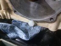
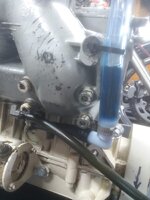
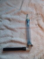
The attached photos are of the prototype unit. In words, here's what was done and I hope you can see this from the photos. The existing 90 degree ell just below the rotary valve cover was removed and replaced with a 1/4 NPT plug. The 90 degree ell just below the exhaust manifold was rotated 180 degrees so it's outlet faced the PTO side of the engine instead of facing forward. I despise the use of clear PVC for any use around a vehicle. However, this being a prototype, it was used as the vertical "filler tube/sight glass." In operation, one can see if any oil is being consumed and, if so how much. Bear in mind that the vertical tube should only be filled no higher than half its height to allow for lubrication oil expansion due to heat (although I think heat expansion to be probably negligible - better safe than sorry). For the same reason, the vertical tube should be vented. Also, the vent should be filtered and protected somehow from water ingress although I did not do this in the prototype but will in Gen II.
Time will tell and updates thereof can be expected in the Spring at the next sea trial. I would truly like to hear of other alternative examples that you guys have thunk up to solve the same issue. Photos would be nice if you got 'em. It will give us something to do while we're waiting for the temps to warm up a bit.


