-
This site contains eBay affiliate links for which Sea-Doo Forum may be compensated.
You are using an out of date browser. It may not display this or other websites correctly.
You should upgrade or use an alternative browser.
You should upgrade or use an alternative browser.
2011 Challenger 180 Tower recommendations?
- Thread starter Fergusj60
- Start date
- Status
- Not open for further replies.
I have not purchased one yet, but have read some additional reviews on it that were outstanding. I plan on buying one, its just a matter of having the time and $. Looks pretty affordable which is good.Hey Macker thanks for sharing...that looks like a great option! did you buy it yet? Install it?
LionOnABeach
Active Member
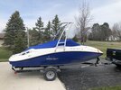
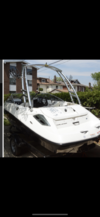
NICE!! did you install it yourself? Looks greatWell i took the plunge and bought it...pics attached...haven’t used it yet!View attachment 53207
Well i took the plunge and bought it...pics attached...haven’t used it yet!View attachment 53207
Nice looking. Looks like your Bimini might fit. If not you might as well get one. Ask me how I know. [emoji106]
I didnt purchase the Bimini top...kinda like the opennessNice looking. Looks like your Bimini might fit. If not you might as well get one. Ask me how I know. [emoji106]
Oh and thank you!I didnt purchase the Bimini top...kinda like the openness
LionOnABeach
Active Member
I bought the same tower, but in the black finish. Just got delivered yesterday. Any reason why you chose the midship mounting location and side mount? And do you fold it forward or aft? There’s no quick release so it looks like you have to pull the bolts connecting the legs/deck mounts.
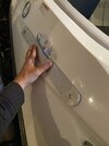
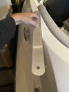
In looking around, there is only one top mount location (see pic). I do like that they included the backing plates for extra rigidity and spreading out the load over a larger area. It also came with four plates that have a slight radius; maybe for mounting on a curved deck? Not sure. I think I’ll mock it up on the back and look at folding, Bimini interference, etc.
In looking around, there is only one top mount location (see pic). I do like that they included the backing plates for extra rigidity and spreading out the load over a larger area. It also came with four plates that have a slight radius; maybe for mounting on a curved deck? Not sure. I think I’ll mock it up on the back and look at folding, Bimini interference, etc.
Attachments
Hey there….so I took the tower to a boat repair place that works on jet boats. I thought the same thing when I saw it…wanted it back a bit further…they said they moved it forward because the boat bowed so much that they the best place for it to sit squarely onto the boat was further up the hull. I’m also really glad they did a side mount and not top mount because the top mount would have forced me to have the cover redone (which cost me nearly $1000 to get made originally two years ago). Lastly they told me that to lower the tower you almost have to take the whole thing apart. I haven’t played with it to see if they are correct on that point. I purchased the tower largely for that reason …its convertibility…so I guess we will see what happens. I’m about to put the boat in the water for the season so have no reason to lower it until fall if I choose to store it in my barn. I’ll be curious about your experience with lowering it…cuz at the end of the day i sure would like that option. About the backing plates…when i called them before the order the told me I’d have to get some from a fabrication place and my installer said no worries cuz they are used to this but when i picked up the boat they told me they had been included in the packaging.
LionOnABeach
Active Member
What do you mean by “the boat bowed so much”? I do understand that getting the tow point closer to the center of gravity of the boat is best for stability.Hey there….so I took the tower to a boat repair place that works on jet boats. I thought the same thing when I saw it…wanted it back a bit further…they said they moved it forward because the boat bowed so much that they the best place for it to sit squarely onto the boat was further up the hull. I’m also really glad they did a side mount and not top mount because the top mount would have forced me to have the cover redone (which cost me nearly $1000 to get made originally two years ago). Lastly they told me that to lower the tower you almost have to take the whole thing apart. I haven’t played with it to see if they are correct on that point. I purchased the tower largely for that reason …its convertibility…so I guess we will see what happens. I’m about to put the boat in the water for the season so have no reason to lower it until fall if I choose to store it in my barn. I’ll be curious about your experience with lowering it…cuz at the end of the day i sure would like that option. About the backing plates…when i called them before the order the told me I’d have to get some from a fabrication place and my installer said no worries cuz they are used to this but when i picked up the boat they told me they had been included in the packaging.
Looks like you’ll clear the windshield when lowering forward. Far as I can tell, it’s just the one bolt holding the joint together and then just rotates forward. Allen wrench is all you need.
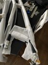
I’m looking at other mounting locations, trying to get it further aft so when I fold forward it’s behind the windshield (and low enough to clear my garage door opener). See pics. Not sure where to put it. Might have to rig something up so I can hang it from the ceiling and play around with mounting locations.
also, I got speakers, but they only have short pigtail wires and I won’t be able to run the wires completely inside the tubing unless I do some drilling and use rubber grommets to cover holes. Hmmmm...decisions, decisions!
Attachments
LionOnABeach
Active Member
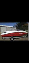
Here are a couple pics of challengers with some other mounting locations with an MTK tower, which is very similar to the Indy. I like the black one and it’s basically my same year boat so this is what I’m going for. I’m just a little apprehensive about having the mounts not on the same plane (front on the top side, rear on the sloping backside by the compartment doors). I think I would have to put a bend in the backing plate, which is another wrinkle. Not hard, just more complexity and I’d rather KISS
Attachments
By “bow” meaning the side of the boat curves so much from bow to stern. I recall when i went their i had some ideas to share with them on placement and i got this look like “dude we have done many of these and we know what we are doing.” I even had printed off a picture of a seafood Bimini tower so they could see where it was supposed to go. But being a trusting person I left it up to them to determine where best to place it. I was really surprised that it was as forward as it was but they said for stability reasons they wanted the bottom of the posts to be square as possible and the position used was the best for that. I was happy that they did side placement cuz I didnt want to have to pay to have my cover modified to accommodate the tower. I’ll have to mess with trying to lower it….do you undo the front posts or the back for that? And you said just loosen one Allen wrench slot on each side to do this? I’d really like to be able to lower it if possible. Really appreciate your threads!
LionOnABeach
Active Member
Ah, yes I get it, thanks. That was one of my concerns, keeping the bases parallel and on roughly the same plane to minimize twisting stress. And also for how these joints work/rotate/swivel. Thank you!By “bow” meaning the side of the boat curves so much from bow to stern. I recall when i went their i had some ideas to share with them on placement and i got this look like “dude we have done many of these and we know what we are doing.” I even had printed off a picture of a seafood Bimini tower so they could see where it was supposed to go. But being a trusting person I left it up to them to determine where best to place it. I was really surprised that it was as forward as it was but they said for stability reasons they wanted the bottom of the posts to be square as possible and the position used was the best for that. I was happy that they did side placement cuz I didnt want to have to pay to have my cover modified to accommodate the tower. I’ll have to mess with trying to lower it….do you undo the front posts or the back for that? And you said just loosen one Allen wrench slot on each side to do this? I’d really like to be able to lower it if possible. Really appreciate your threads!
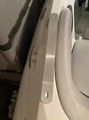
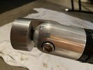
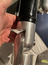
You can do either, but I think undoing the rear and folding forward is what most do. Yes, just a big Allen wrench (came with the tower) and a bolt that holds the base end of the joint to the leg end of the joint. The instructions say it won’t just fold down and won’t be super loose, but you should be able to push it down. Which makes sense if all four bolts are tightened during install, there shouldn’t be a lot of play. Here’s a pic of the joint with the bolt.
Attachments
LionOnABeach
Active Member
So about that bowed hull...now I see why the MTK has HEIM joints! Also, the comment by your installer about taking it all apart to lower makes more sense.
So I was mocking up my mounting location and the side mount is going to be best. One, I can mount it further aft so it *could* fold forward and sit behind windshield and sit lower. And two, better for keeping the mounts parallel. But...a couple things.
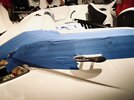
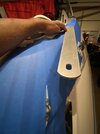
First, there’s not a single stinking hard angle on these boats from which to measure! All angles and radius so just making sure you have a mounting location that’s the same on both sides is a PITA. I used a couple places where there were corners where I could pull a tape, but then I had to go find a flexible tape measure - like the kind for fitting clothes - to make it around all those curves. I actually had to measure and mark a couple reference points so I could lay it out. I used the backing plate to mark where the bases would go and then traced the bases where they should go. I was within less than an eighth of an inch when all done, so I was good with it. The second issue - the radius (bow) of the hull. Holding up an upright on the mounting locations as-is puts a slight rotation in the upright. Due to the radius on the hull sloping inwards as you go aft, the top of the upright rotates out (as looking from the stern). The top U-shaped piece of the tower has 90 degree bends, and if mounted as I laid out, the piece would need a couple degrees greater than 90. The uprights are stout and have a couple cross braces so I’m not sure you could twist it enough to muscle it in. And even if you could, there will be extra stress on the mount, decking and tower. And unless you have a mandrel to do it, you’re going to mar up the top piece.
Finally, when you side mount, the joint is such that the rotation to fold forward needs to happen across two axis of movement instead of just one. The upright mount needs to swivel (rotate clockwise), while base mount moves along the perpendicular axis. Basically the joints are opposed 90 degrees in the side mount while they are inline on a top mount. If everything is tightened down, it might be a problem trying to get those the right rotation with out loosening everything (like your installer mentioned).
Sooo...if I still want that rear mounting, what do? I think the easiest is to machine a couple 2.25” OD by about 2” long spacers that mount between the deck and the base mount. Granger has some 6061 aluminum stock that I can get for $30 (https://www.grainger.com/product/GRAINGER-APPROVED-Corrosion-Resistant-6061-Aluminum-2EYF8) that I would just have to cut to length and drill out the center. But then I’ll need longer bolts and I’m adding length, which will put more force on that bolt. I’m not too worried about that though since it’s only two inches, the load won’t be crazy and stainless 1/2 in bolts are strong and easy to come by. But taking it down, you will probably have to pop all four bolts that go through the joints to lay it down. I think I’m okay with that bc once it’s all together, and with one of my boys, we could do it in a matter of minutes with an Allen head in my drill.
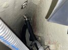
That’s my plan at least. Cut some spacers out of the rod, drill out, and then do a bunch of fit testing. The bases on the uprights need to be as parallel as possible. See the pic where I have the backing plate set inline with where I think the line needs to be. Again, finding solid, shape angles to measure from on this boat is a pain!
Attachments
Last edited:
Wow that’s really far aft but i mean if it works go for it…I’d rather have it back further because now i have to look at adding exemptions to my pull ropes cuz i lost a good 5-6 feet with the way they positioned it…but I can’t dis them because I’m a banker and have absolutely no mechanical mind for this stuff lol
LionOnABeach
Active Member
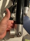
Correct. Both of us will have to take all four out and then just set it down on the boat. See pic for comparison: inline (top mount), opposed (side mount). In the pics, lowering would be the upright moving away/forward.Oh and if i interpret your engineering vernacular correctly you’re telling me that neither of us will likely be able to lower the tower simply by loosening the Allen fasteners…or is it specific to me?
Attachments
LionOnABeach
Active Member
Yeah, nothing wrong with your location and it makes sense to me. I’m just bull headed in what I want, lol. And I don’t know how they got access to mount and in the back it’s wide open.Wow that’s really far aft but i mean if it works go for it…I’d rather have it back further because now i have to look at adding exemptions to my pull ropes cuz i lost a good 5-6 feet with the way they positioned it…but I can’t dis them because I’m a banker and have absolutely no mechanical mind for this stuff lol
- Status
- Not open for further replies.
Similar threads
- Replies
- 0
- Views
- 164
- Replies
- 11
- Views
- 499
- Replies
- 2
- Views
- 482
- Replies
- 2
- Views
- 462
- Replies
- 0
- Views
- 156
Share:


