• This site contains eBay affiliate links for which Sea-Doo Forum may be compensated.

1999 Sea Doo GTX RFI - Battery Not Charging

Status
Not open for further replies.

LIBoater

Member
Firstly, thanks for the add. I've been boating all my life, but this is my first PWC. She didn't run when I bought her, but a new fuel pump, spark plugs and battery and she fired right up. That's the good news. The bad news is the "Low 12V" warning appeared on the dash.

I charged the battery and started her again, this time I connected the volt meter to the battery. The meter holds steady at ~12V. No increase with increased revs, which indicates to me that the battery is not charging. I've read all sorts of horror stories about stator replacements etc, so I'd rather start simple and diagnose one step at a time.

Can anyone give me a step-by-step troubleshoot? Fuses? Rectifier? Stator etc... where should I start?

Thanks in advance!

Simon
 
It’s most likely the voltage regulator and verify common on the RFI. So common that OSD Seadoo actually sells an upgrade kit for yours to the stronger 4-tec regulator.

If the voltage doesn’t increase with rpm it’s the regulator.
 
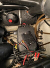
Thanks... just checking... is this the original rectifier, or the upgraded version?... how can I tell?

Concerned this may have been a "known" issue and the previous owner tried the low hanging-fruit first, by swapping out the rectifier, but if you're saying that zero change to the volts on the battery on increased revs points to the rectifier, I'll swap that out and see.

Also, are there any fuses in line that may have blown? Can't see any obvious.

Thanks again
 

Attachments

  • IMG_4036.jpeg
    IMG_4036.jpeg
    478.1 KB · Views: 83
Not for nothing...but I see battery jumper clamps in your photo. DON'T jump a seadoo battery while the battery is connected to the machine....not worth the risk of damaging any internal circuitry.

IDNK the answer to the original or upgraded VR based on your photo...sorry.
 
Not for nothing...but I see battery jumper clamps in your photo. DON'T jump a seadoo battery while the battery is connected to the machine....not worth the risk of damaging any internal circuitry.

IDNK the answer to the original or upgraded VR based on your photo...sorry.
They’re not jumper cables they are the clips to the trickle-charger.... I heard about the pitfalls of jumping jet skis!

I have ordered the upgraded rectifier and will try that first... not relishing the idea of stator replacement!!!

Thanks
 
I have "struggled" with rectifier replacements on my '96....on my 3rd one....hopefully 3rd times the charm....Good Luck.

Stator replacement can be a challenge.....hopefully you won't need to take that path......you can test the yellow wires for resistance to see if the stator is OK.....there is a procedure in the manual....not difficult at all.
 
I use the regular Rectifers at a price of around $25 and they work just fine. I keep a few in stock. They replace easy peasy on the RFI. There is also a fuse that can blow and will not let the battery charge. It's up front near the MPEM on the left hand side looking forward. It's at the top left all by it's lonesome.

I think the RFI is my favorite Seadoo engine. They are sweet make good power and anyone can hit the button and go.
 
Last edited:
I use the regular Rectifers at a price of around $25 and they work just fine. I keep a few in stock. They replace easy peasy on the RFI. There is also a fuse that can blow and will not let the battery charge. It's up front near the MPEM on the left hand side looking forward. It's at the top left all by it's lonesome.

I think the RFI is my favorite Seadoo engine. They are sweet make good power and anyone can hit the button and go.
Thanks... I'll have a look for the lonely fuse and double-check that... I've ordered the beefy rectifier from OSD Parts... hope is not a strategy, but let's hope that fixes it... if they blow that easily, I might take your advice and keep a few $25 rectifiers in the toolbox!

Will let you know how I make out and thanks again for all the swift advice!
 
I'm not implying that the correct less costly rectifers don't work well. I just restore a lot of skis and when I need one I have it. I've read about people complaining they had trouble with the so called upgraded ones. Go with whatever makes you comfortable. :)
 
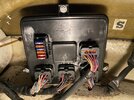
OK, so where is this elusive fuse for the rectifier?... I can’t see one that stands alone and all the ones shown here are not blown... thoughts? Thanks in advance
 

Attachments

  • CA13D291-3057-436F-AE1C-D78563D63D11.jpeg
    CA13D291-3057-436F-AE1C-D78563D63D11.jpeg
    399.3 KB · Views: 66
Hmmmm... That is a different MPEM location than I'm thinking. I might be thinking GTI. Go into the rear Electrical Box and check the fuse in there if you have not already. The fuse is gonna be between the charging circuit and the battery. Probably the red wire on the solenoid Check the wiring diagram.
 
Hmmmm... That is a different MPEM location than I'm thinking. I might be thinking GTI. Go into the rear Electrical Box and check the fuse in there if you have not already. The fuse is gonna be between the charging circuit and the battery. Probably the red wire on the solenoid Check the wiring diagram.
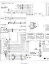
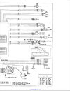
Thanks Gene... looking at the wiring diagram (attached) I don't think there is a fuse between the magneto and the rectifier... new rectifier should be here in a couple of days so hoping it's plug and play... will update this thread once installed for the benefit of any who follow.
 

Attachments

  • IMG_0080.jpeg
    IMG_0080.jpeg
    259.4 KB · Views: 56
  • IMG_0079.jpeg
    IMG_0079.jpeg
    217.7 KB · Views: 53
HELP!... I finally got round to installing the new (industrial-strength) rectifier and................................. no change!!!!... I started her up and had my DC volt meter across the +ve and -ve terminals on the battery... the meter did not move from 12V... I am assuming (dangerous) that the next part to swap out is the magneto, but is that a difficult job?... might be time to call in Seal Team 6... any additional suggestions?... also, if I ask my local dealer to change the magneto (if it's beyond my skills/time), what should I expect to pay?
 
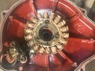
I'd verify everything before I changed the magento. Take resistance readings and PAY NO ONE to replace it. It's easy just be gentle loosening the bolts. Spray some penetrant on them. Make sure your wires and connectors are good. Check all the fuses. The magneto is inside the cover like the picture but the picture is of a carb 787. Good Luck!
 

Attachments

  • 787 Mag Cover painted.jpg
    787 Mag Cover painted.jpg
    319.3 KB · Views: 54
I'd verify everything before I changed the magento. Take resistance readings and PAY NO ONE to replace it. It's easy just be gentle loosening the bolts. Spray some penetrant on them. Make sure your wires and connectors are good. Check all the fuses. The magneto is inside the cover like the picture but the picture is of a carb 787. Good Luck!
Thanks Gene... I'll need to do some reading and research to understand what resistance I should be getting across what wires... any suggestions?... or at least where to start looking?... I read somewhere that I need a special plug (adaptor) to get readings at the magneto?... per the wiring diagrams I posted above, there's not much between the magneto, rectifier and battery, hence why I think my options are narrowing... if anyone has any suggestions as to what (resistance) readings I should look for in the wiring I'd be very grateful.
 
It's in the manual. Basically all three of the yellows are gonna read the same resistance unless you have an issue. Then you check all the yellows individually to the ground wire. Then red and black. If anything is shorted you have a problem. Check the black to ground also. I'm just going from memory. I think you could take a AC voltage off the mag with the engine running. There is a reading for that also. The rectifier just changes the AC voltage to DC so.... open the manual and give it a whirl. :D
 
The schematic shows 3 fuses in the rear electrical box. One of them is a 1A fuse. Did you check them?
 
The schematic shows 3 fuses in the rear electrical box. One of them is a 1A fuse. Did you check them?
Yup... pulled all 3 fuses 1A and 2 x 20A... all good... she has a new battery, new rectifier, all fuses are good, so I guess it's the stator... I just spoke with my local repair shop and he said 2 things:
1. You need to pull the engine
2. No one works on 2 strokes anymore, so I guess it's down to me
Do I REALLY have to pull the engine?????
 
Nope, don't pull the engine. Remove the exhaust pipe and the mag engine mount completely. Stick a block of wood under the engine but far enough back that the weight won't be on the cover you are removing. Two dowel pins align the cover so stick a flat blade screwdriver in those little slots and twist gently. the cover will separate. The stator is inside the cover just like the picture I posted. I've pulled the stator with the engine in place.

Oh yea, you'll have to disconnect the cooling water lines a the bottom of the cover and the sensor at the top. Be careful not to break the plastic fittings on the cooling water cover. Be gentle. If you tear that lower hose you will have to get under the engine to replace it so be careful. Good Luck!!

If you pull that engine you'll creat 5 times the amount of work.
 
Oh be careful not to let the weight of the engine sit on the little bronze fitting. That will ruin your day. Stay away from the lower cooling water line. Better to let the engine sit on the cover or block it up someplace else. You're only taking the weight off. not really lifting it and it isn't that heavy anyway. Be gentle.
 
Is there any voltage on the RED wire OUT of the rectifier? That is the only line you care about....that RED wire out of the rectifier should be 14V +/-, sending a charge back to the battery...through the fuses.....if the voltage is there and the fuses are good....could be bad wiring.....internal shorts/corrosion....take nothing for granted....test every piece of wiring for continuity....methodically.

If you gots no voltage out of the rectifier, then check for AC voltage INTO the rectifier (from the magneto). The rectifier simply converts AC to DC for the ski charging system (trickle charging the battery) and voltage needs (guages, whatnots) while running.
Looks like I may have one (or two) more roll(s) of the dice before I pull the stator...

Firstly, to check the DC (red) out of the rectifier is it as simple as putting my red meter probe into that wire and the black to ground somewhere, or the -ve on the battery?

Secondly, checking ac voltage out of stator, is that something I can do at the rectifier end of the wiring? If so, what wires do I connect my tester across? If it has to be at the stator, same question; which wires?

Thanks!
YES, to question #1.....find a way to probe the RED wire (unplug the rectifier connection and probe the pin) out of the rectifier for DC voltage (14vdc) to any convenient ground or battery black (I use long alligator clip jumper wire extensions to reach things around the ski)

To test your magneto....ski OFF, unplug the magneto connection....you should find (I believe from memory).... .6 ohm resistance between pairs of yellow wires....SO, label the yellows 1,2,3, test 1-2,1-3, 2-3. If the resistance is correct across the wires, chances are good the magneto is good..... (all pairs should be the same or close to within .1 ohm....I think I remember that correctly)

If the ski starts and runs, the coil pickup off the magneto must be good

It could boil down to the actual physical wires themselves....so test plug to plug (end to end along the wires for continuity)...assume nothing is good until you PHYSICALLY verify it....visual checks for electrical work are worthless
 
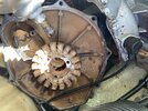
I bit the bullet... and I think I found the problem (no kidding!) see attached photo... stator looks like it needs more than a dusting off!!!... thanks to this great video
I summoned up the courage to pull the stator plate without pulling the engine (or removing the oil lines)... it’s a mess... no o-ring (which made removing the plate “difficult”), but obvious historic water damage (although bone dry now)... the fun continues as the lower M6 bolt is seized in place, so had to grind off the head (even then the stator needed some serious “persuasion”... the rest of the bolt is currently soaked in PB Blaster in the hope that a pair of vice grips will finish the job tonight... incredibly my local Sea Doo dealer has an o-ring and a few M6 bolts lying around, so hoping to complete the job tonight... will update later/when complete
 

Attachments

  • 2C827170-95C9-4D1B-AF88-45B2F874A7EB.jpeg
    2C827170-95C9-4D1B-AF88-45B2F874A7EB.jpeg
    413 KB · Views: 53
Quick additional question... the oil pump shaft looks especially flimsy... any special techniques for ensuring it aligns on the pump and/or shaft?... assume connect pump end first, but interested to hear if anyone’s had experience?... wouldn’t want to get all this way and screw up the oil delivery system at the final step... thanks
 
Status
Not open for further replies.
Back
Top