Get a cup of Joe, very long post!
The topic of the Counter Balance shaft of the 787 and 951 engines has been brought up on more than one occasion. In the past, information that has been quoted, normally is that of the manual. A lot of the time, if I make a statement that is not in the manual, I will add, “in my opinion”. This way, it gives the member the idea that my theory may be incorrect, or your views are different, that’s human nature.
I know this post is going to be a long one, because to get my point across, I think it’s necessary for a little background of my mechanical knowledge. I have extensive schooling in theory, principle and engineering training with many certificates of completion. I attended college but like so many others, ran out of money/had to support myself/ it got boring…..and a lot more reasons that are simply generic, “I quit”.
I have worked in the engineering field for over 30 years, professionally. My specific career in what “makes my money” is steam generation. The operation and maintenance in Babcock and Wilcox boilers, turbines, pumps, gears, valves, compressors, generators, water purifiers, automatic PLC applications and computers to name a few. I’ve attended and completed chemical analysis schools for testing and treating water, fuel and lubricants for viscosity, water, flashpoint, BSW (bottom sediment and water) and much more.
Since I was a youngster, I was always fascinated on how something worked. Back then, I tore stuff apart, to see it never run again. As I grew older, the idea of tearing something apart to make it run again, or run better and faster, started my challenge in the mechanics of the internal combustion engine. I started like most other mechanics, 3 or 5 horsepower Briggs and Stratton and Tecumseh engines. Removing and replacing the pistons (which is when I learned what a press was) and lapping in the valves (remember how lawnmowers always backfired, shooting a flame from the muffler several feet? I learned that 80% of the time, it was from a burnt valve and I could fix it by lapping it in to seat the surfaces).
In my mid teenage years, my skills moved on into motorcycle engines and 2 stroke boat motors. My success rate in repairs was at best, 75%. There are just some problems that can’t be fixed.
By the time I was 16, I was rebuilding Chevy 283, 327, and 350 cu. in. motors. I didn’t mess with any Fords at that time. Back then, you were either a die hard fan of Chevy or Ford, not both. This was my beginning into high performance building (or as it’s called now, “mods”).
At 18, I joined the Navy and became a steam propulsion engineer. This is where I met the competition that made me want to be the perfectionist that I am today. I learned to do it right the first time, because to do it twice was a waste of time. I also learned that to be the best, I had to stay one step ahead of my mates. I advanced very quickly to E-6 (military jargon for supervisor) because of my drive and determination to constantly learn and keep up with, the ever changing environment of engines. I know, there are some old timers here who remember those engines I spoke about in the last paragraph and how we were constantly trying to change with the ballgame. The automotive industry changed quickly to keep us “shade tree” mechanics from building our high output engines by changing them from cubic inch to Liter. Then, they started removing the standard sized nuts and bolts to torx heads or star bolts, removing the carbon points to electronic ignition (which was a God send), then on to the computer controlled engine management systems that we see today. To continue to work on engines, you had to constantly change your tools, once again, to stay one step ahead of the manufacturers. I always felt it was because we were putting dents in the dealerships repair business (they were losing money), so they made changes to make it harder for us to help make a little money on the side. If you are old enough, you may recall the service stations where you pulled in to get gas. The guy filled your car, did your windows and if you had a problem with the engine, he may hear it, tell you what it was and make the offer for you to pull into one of the two bay doors of the mechanics shop (air and water was free then too!). Back then, all service stations had a mechanic, Texaco, Shell, Exxon…..all the major players. Well, now you just stop, get gas and buy a coke in the store. There are no mechanics anymore; you have to take your vehicle to the dealer or another franchised repair shop.
Now, the counter balance shaft. Robin and I both have two different opinions on how this system is set up. In 1995, when the first 787cc motor with a counter balance shaft came out (the XP-800) it was necessary in the evolution of the engine, to offset the vibration caused from the larger stroke of the engine. At the time, the 85 horsepower 717cc engine was the strongest engine Rotax made but required no counter balance other than what was already present on the crankshaft itself. Car engines use what’s called a “harmonic balancer” to counter the forces of rotation created from combustion of the engine. The reason why is because the crankshaft is not one straight metal shaft. For the pistons to travel up and down, they have to be offset from center. The explosion that takes place in the engine creating the downward force on the crankshaft, creates vibration. The vibration has to be controlled, or it will destroy the engine. That’s why we came out with a way to cancel these forces, with something providing opposing weight of the crankshaft.
Now, we move into gear cogs. This is where Robin and I seem to have our strongest difference in opinion. A cogged gear has one drive or power gear. The other gears and shafts are reacting to the main power gear for what ever purpose it was designed for, usually called idle gears. A gear cog may or may not have a ratio. If I counted right, the cog gears of the counter balance shaft and crank shaft are 44 teeth each. If a cog has a different ratio, it will have a different number of teeth and also be either larger or smaller in size.
Not all cogged gears are lubricated. The speed of the shaft is normally what decides on the need for lubrication. As we all know, the purpose to lubricate is to minimize heat caused from friction. The cogs of a cuckoo clock, do not have a lubrication system. Cogs in friction cranes and other open machinery with cogs, do not have lubrication due to the speed in which they work. There will be a bearing at the center of most cogged gears, normally lubricated by grease through an external grease fitting.
Enclosed cogs that run on a higher rpm scale and create high torque are normally lubricated by an oil sump, with a “flinger ring” attached to the shaft. This flinger ring is a loose ring, that flips around the shaft, dipping and splashing the oil onto the cogs, to keep them from building to much heat. With heat, comes expansion. Usually, most enclosed cogs have very close tolerances to the casing in which they are enclosed. Once expansion takes place, the gears will wear into each other and wear away. They may also come in contact with the casing and bust out the side, as was evident in a post Robin made several months ago from a website (seadoosource I believe).
In the manual that Robin points us to, it shows the mechanic filling the counter balance shaft with injector oil (1 ounce) from a hole, that is internally ported from the PTO side of the engine block, into the closed area of the crank and balance shaft cogs. What the manual doesn’t show us, is when that cylinder is assembled, it’s practically sealed from the combustion chamber. With it’s position in relation to the cant of the engine, the hole is pointing up. Which makes me inclined to believe it is more of a vent, than it is a retainer or supplier of oil to the reservoir. If you’ve seen enclosed cogs in other mechanical applications, then you’ve no doubt seen that they are vented. Because oil puts off an explosive vapor when heated, some applications have a static mesh screen that eliminates the explosive hazard to an inside environment with a small electrical charge.
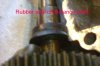
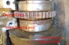
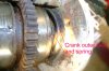
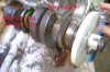
In the Rotax engines that followed, that have the balance shaft, from 1998 and newer, the balance shaft has a plug, for removing and checking the oil. In the 1998 manual, it states this must be checked every 100 hours or once a year. In the manuals from 1999 and on, it states to check this oil every 50 hours and/or 100 hours (seasonally). Your suppose to dip a piece of wire into the hole to see if there is oil and if that oil has water aerated in it (which will be yellowish in color). If you look at the pictures I’ve attached to this post, you’ll see that there is a double, rubber seal on the counter balance shaft inboard (picture 1) and not shown, is a rubber “0” ring and seal plate on the outboard side. On the crankshaft, there is a seal (similar to the rotary shaft) that covers the inboard roller bearing (picture 2, I didn’t label them, but the two main roller bearings are visible too). There is an obvious rubber seal, which is pointed out in the picture 3, that is on the outboard area of the PTO side. This area, mechanically, is sealed in all directions except the very top, where the hole is that Robin is pointing out (picture 4). If you can imagine the counter balance shaft and the crank shaft in the shape of an 8, laid down (which would be the configuration of the engine installed), the one ounce of oil is in the bottom of those two recessed areas. The gears are only splashing oil, to keep them wet. This keeps the heat down from a rotating shaft in excess of 7000 revolutions per minute, to a minimum.
The year of 1996, the manual calls for the use of injector oil. I didn’t see a supplement changing this, but in 1997 and on, they state that you use an SAE (Society of Automotive Engineers) 30 weight motor oil. Although, I haven’t looked at the weight of the injector oil, I’d have to say it can’t be any greater than 5. Which, really isn’t sufficient to cool the cogged gears at that rpm. Over filling the cavity with more than 1 ounce, will lead to greater expansion of the oil as it heats up and could cause a seal to leak, losing the oil inside the chamber, causing it to destroy the gear cogs.
The last point I want to make is this. Robin believes, for the moment, that the oil is maintained through normal operation of the engine, through the injector oil. For me, that isn’t logical. Why would the manufacturer have us put in and check oil yearly, for a specific oil, if we were allowing a supply of a different viscosity of oil to supply this system: since when do we concede that two different oils can be mixed? Also, why would we be isolating the gear cogs from the crankshaft area with mechanical seals? There seems to be a redundancy here, of purposefully isolating this system, as we do the rotary chamber. Can injection oil reach this chamber? Because it’s open, I’d think so. But, how much oil do you think is left over from combustion? I’ve never notice any film floating on the surface when idling like I did when I premixed my older outboards. Our variable rate injection is designed to lubricate the bearings as it passes through from the intake into the combustion chamber before being ignited with the fuel and burned off.
I’ve also included a picture of me spraying parts cleaner through the hole Robin has pointed out. Look closely and you’ll see the mist coming out from behind the crank cog. So, the hole IS internally ported to the cogs. The last picture is one I meant to make twice, one from the outside and one from the inside. As you can see, the button on the casing looks like a plug. It isn’t. It’s smooth on the inside casing. I think the research and development engineers had already determined it would be later built with an oil plug, but this model and others I’ve heard from in the forum, have this in their 787’s. You can drill this out and tap it with a plug, if you really wanted to (engine casing seperated of course).
The very last thing I’d like to add. The balance shaft and engine you see, is from a 1996 Challenger that I have in my shop. The original owner forgot to put the plugs in the boat and it ingested water. When I got it, I tore it down as a learning experience. When I split the casing, it had motor oil in it at the cogs. I can’t say how much because I spilled it out when I split, then moved the casing. At that time, I was unaware of the oil in the balance shaft. This was my first engine, before I even had a manual. For the last two years, I’ve used it for trouble shooting my problems and of course, your problems here in the forum. The thread, a look inside the 787, is from this engine.
This post is of my own opinion that was formulated from the manuals and my reasoning logic of the inner workings of seals, bearings, cog gears and shafts. It's by no means, a 100% proof positive post from a Seadoo/Rotax engineer. Which, by me, would be the only way I could find a true answer.


")