nsoley
Member
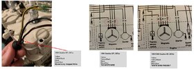
Interesting one... Bought a 1994 SeaDoo SPi with the 587cc engine. As part of the full restoration I am doing, I wanted to ensure (before the engine goes back in) that the Stator resistance checked out OK as replacing the stator when the engine out is likely easier.
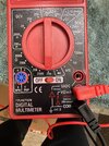
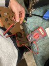
I took my multimeter, put it on the 200Ω setting, placed the red and black probes to the YELLOW and YELLOW/BLACK wires. The reading came back 4.3Ω when the specification is 0.05Ω-0.6Ω
Am I missing something here? IMG-8886 shows the multimeter setting. IMG-8885 shows the measurement.
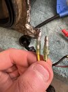
Would the heat shrink play a part in higher resistance? (IMG-8887) I am debating cutting the wires, and measuring bare copper on both YELLOW and YELLOW/BLACK wires without the heat shrink and male terminal. Thoughts?


