Doug Overkill
Active Member
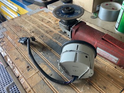
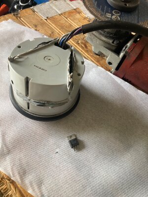
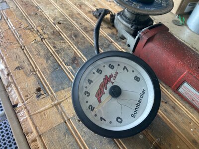
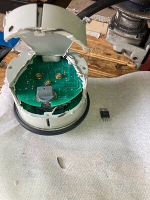
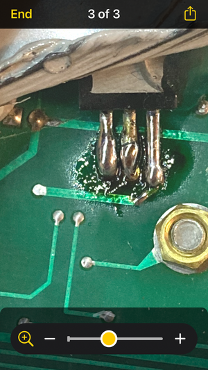
Here is a strange one, or at least is to me. 1997 Challenger 1800 with twin 787’s. Recently the left tachometer just stopped working. No needle movement at all. The right works fine. I was trying to determine if it’s the signal from the MPEM or the tach itself. In the console behind the dash each tach is plugged in with a 3 wire connector. Both connectors have Black and purple wires that read 12.8v when you wake up the MPEM by quick pressing the starter buttons. The 3rd wire is grey (1 with tracer).
Here’s where it gets weird. When I swap the 2 connectors and start both motors, the right gauge still reads the RPM from the right engine. The left tach still doesn’t move. Swap them back and right gauge reads right engine. Huh?
If the connector with tracer (right motor) is plugged into right tach it works as it should. Both when the left connector is plugged in or not. If I plug that right connector into the left gauge nothing happens if the left is unplugged. When I add the left motor connector to the right tach, then the right tach displays the right motor rpm. Again huh?
So confused. Anyone have this experience? Anyone have any ideas as to what to do? It is very helpful when driving this boat to have both engine tachometers working.