Are you referring to my comment about wiring around the MPEM?
You can find most of the Seadoo manuals at
SeaDoo Manuals - FREE PDF Download! . At the end of the service manual you will find the main circuit diagrams for your Seadoo.
This is how the VTS unit works: There is a low current circuit that activates two relays that route the high current 12v (red/purple & black) to the motor. When the toggle switch is set to UP then the UP relay is activated and the motor pulls the plunger in. As the plunger goes in a magnet passes over a series of small magnetic switches, each attached to a resistor of increasing ohms. When the motor has driven the plunger up to a certain point, the last magnetic switch deactivates the relay, thus preventing overrun. When the toggle is moved to Down, the Down relay is activated sending current in the opposite polarity to the motor. As the plunger moves out the magnet activates one magnet switch after another each time sending a decreasing voltage (via purple/white wire) back to the console display. When the plunger reaches the last magnetic switch the relay is deactivated to prevent overrun. This logic is powered by 12v sent to the VTS module from the MPEM via the green/white wire.
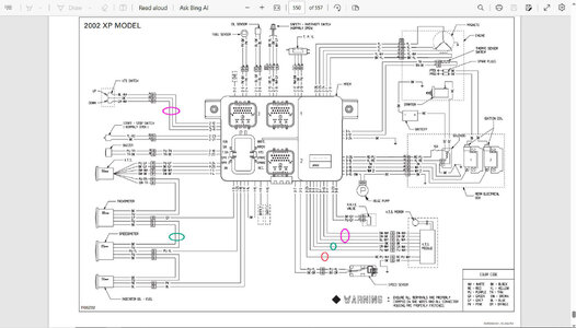
Test MPEM circuitry: (1) make sure the red/purple wire is hot (red oval) all the time. If not disconnect the 2 wire connector and run a clip lead from red/purple wire to the positive side of the battery and a clip from the black wire to the negative side of the battery. Test.
(2) make sure the green/white is hot. This wire powers the logic in the potted VTS module. Hook a test lamp to ground and the the green/white wire from MPEM. Put security key in. Light should stay one till the MPEM times out. If not, run a hot wire from battery to the green/white wire and test the VTS. If that fixes the problem, you can tap into the MPEM 12v circuit by splicing into the purple wire that powers the instruments. See the green ovals. To test the UP/DOWN toggle circuit disconnect the 6 pin connector and run a clip lead from the positive side of the battery to the brown/black wire from the MPEM. Hook your test lamp to the brown/white and ground. Press the up/down switch. The light should turn on in one position or the other. Hook your test lamp to the black/white and ground. Press the up/down switch. The light should turn on in one position or the other. If not, you can wire around the MPEM by cutting and splicing the wires in the pink ovals.
If the MPEM circuits check out and the VTS still doesn't work then you most likely have a failed VTS module. Usually this can be repaired but it is a major task getting the PC board out without destroying it. Even then I would not recommend trying to do this unless you know how transistor switching logic works. My experience has been that the switching logic is usually ok and the fault is in the board itself or the relays. Water can get below the potting material and cause the small conductors to corrode or a high current relay gets struck. When that happens the motor drives the plunger to its limit and cuts off power.
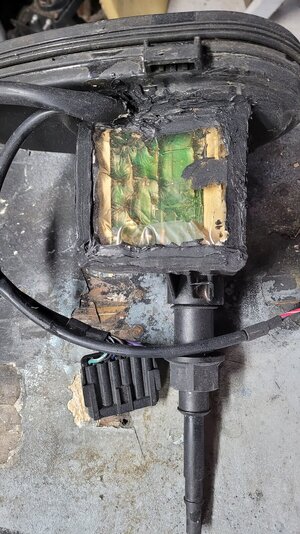
The second attached photo shows one of the VTS units I rebuild. After I fix the logic I put the PC board back in the box and line the box with a kitchen plastic wrap. I then pour a layer of clear epoxy and let it dry. This provides a tight fitting new cover for the PC board. I seal it with RTV. Not the prettiest thing but it works.
If you need additional help, please ask. Jim


