• This site contains eBay affiliate links for which Sea-Doo Forum may be compensated.

2013 RXT 260x do I need new wiring harness and/or ECM

Status
Not open for further replies.

FLgator

New Member
I'm baaaak. Still having problems with my ski showing check engine and IBR lights and going into limp mode....no rhyme or reason as to when. Could be 5 minutes or 45 minutes into a ride. Have previously posted issue and some suggestions were to check thermostat or run with gas cap open. The gas cap open worked for a while, but still went into limp mode....haven't been able to really check thermostat.

Anyway, took it again into the dealer and the estimate stated there were 19 occurances of one code--IBR CAN BUS curcuit/ECM failure. Check wires/connections and/or replace ECM. 1st step replace bad wiring harness and then ECM if needed.

The quote for the wiring harness was $1280.00 and no quote for an ECM. I hate to be putting all this money into this ski and still have problems. I really can't sell it with known issues like this, so my hands are somewhat tied. Wondering if anyone else has seen this? What a new ECM would cost? If I were to sell it, wondering what amount I should discount it if I were to find a buyer interested in a unit with known issues?

Thanks for any ideas or input.
 
Well, it's obvious the dealer has no idea how to troubleshoot a CAN bus problem. Throwing parts at it is not diagnostic work. You need to find a shop who can properly troubleshoot a CAN network problem.

Here's some suggested reading

https://support.maxongroup.com/hc/en-us/articles/360009241840-CAN-bus-topology-and-bus-termination

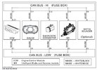
Here's a sample network topology for a 2017 GTR 230 (my current ski)

Can bus network.JPG

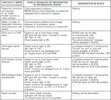
Here's a sample of a diagnostic tree.

Fault Tree Can Bus.JPG

The Sea-Doo network is not nearly as complicated as a car, but you would troubleshoot it in a similar fashion. You have to have a break out box to connect to the diagnostic connector, and then you need a lab scope (and somebody who knows how to use it) to look at the data packets being transmitted over the network. In a car, Can Hi is 2.5-3.5 VDC; Can low is 1.5-2.5 VDC. The technician will look for a consistent voltage wave form over the network within the Sea-Doo specified voltage range. If there are abnormal patterns, then the technician will disconnect one module (electrical connector) at a time until the wave form returns to normal. For example, if you see an abnormally high (voltage) wave from, and you disconnect the information center and the pattern returns to the specified voltage; that means the information center is faulty in relation to the network.

Go to the 21 minute mark in this video to see what I'm talking about as far as the wave forms go. If the dealer doesn't have a lab scope, they cannot troubleshoot your problem properly.


Now that you've brought this to the attention of the forum, I'm going to contact CAN DOO to see if they make a breakout box for CAN Bus.
 
Last edited:
I just got off the phone with Dennis at CANDOO, and they don't make a breakout box for network troubleshooting, but he said they have seen network issues caused by cracked information centers (water gets in and short stuff out), and IBR modules because water gets into the electrical connector and causes corrosion. Remember, Can voltage is very low, so corrosion can cause big problems.
 
From looking a little more at the ski's topology, it appears the two terminating resistors are in the ECU and the IBR. The Sea-Doo manual doesn't state it as such, but we have the picture.

However, if you look at the schematic, I see one of the terminating resistors in in the diagnostic connector (red arrow)

Sea Doo Diagnostic Connector.JPG
Watch this ... it's only 2 min.


After looking all over the schematic, I don't see another terminating resistor, but I'll bet it's in the fuse box because this looks like the "gateway" module for the network.

Sea Doo Fuse Box.JPG
 
Last edited:
From looking a little more at the ski's topology, it appears the two terminating resistors are in the ECU and the IBR. The Sea-Doo manual doesn't state it as such, but we have the picture.

However, if you look at the schematic, I see one of the terminating resistors in in the diagnostic connector (red arrow)

View attachment 60556
Watch this ... it's only 2 min.


After looking all over the schematic, I don't see another terminating resistor, but I'll bet it's in the fuse box because this looks like the "gateway" module for the network.

View attachment 60557
mkov608....Wow, thanks for the quick and very detailed response to my questions. Diagnostics is beyond my level of mechanical aptitude, but you did mention corrosion -----I spoke to the tech today and he said there was what they call "green corrosion or green death" which is quite common down here in FL and on these models of jet ski's that have most of the electronics towards that back of the unit. He said very difficult to pinpoint exactly where the green death is as it spreads due to high humidity and water and can ruin a wiring harness.

I wish you were local ( Pensacola, FL) as your knowledge is worthy of a visit, but my choices are somewhat limited for gold-type service. I will talk to a friend who is into PWC's to discuss your suggestions and my alternatives to fixing and selling this unit.

Thanks again for the information!
 
Well, I am in Pensacola ... Milton really, but close enough.

Looks like I was wrong about the fuse box being the gateway module. It's just a bus bar for the network (where everything connects). I found both network terminating resistors tonight (in my ski). One is in the cap for the diagnostic connector, and the other is in the ECM. I even connected my lab scope to look at the data packets, but I didn't like what I saw on Can Hi, so I have to figure that one out.

Just like a car, Can Hi on my ski is 2.5-3.5 VDC and Can Low is 1.5-2.5VDC.
 
Last edited:
Well, I am in Pensacola ... Milton really, but close enough.

Looks like I was wrong about the fuse box being the gateway module. It's just a bus bar for the network (where everything connects). I found both network terminating resistors tonight (in my ski). One is in the cap for the diagnostic connector, and the other is in the ECM. I even connect my lab scope to look at the data packets, but I didn't like what I saw on Can Hi, so I have to figure that one out.

Just like a car, Can Hi on my ski is 2.5-3.5 VDC and Can Low is 1.5-2.5VDC.
Mk....Ironically I also live in Milton :). My PWC is currently at Pensacola Motorsports waiting for my decision to either move forward with the wiring harness or pick it up. If you are interested in looking at this unit, I would like to discuss.
 
What are the odds!!!??? IM me, and we'll connect. No sense in letting Pcola Motorsports throw your hard earned money at it by loading their parts cannon and firing.
 
I would pull the ibr motor,,,when the motor or module starts to go,,,they throw all kinds codes,,,according to other posts on here.
 
FLGator is bringing the ski over today. My intent it to make a YouTubie video to show the community how to troubleshoot Sea-Doo Can Bus problems with my lab scope & multi-meter. I was never a big fan of throwing parts at a problem (and most of you aren't either because parts are so freaking expensive), and there is a lot of good information on the internet on dealing with communication issues across the bus.

So, if there's something you want to see in the video, let me know.
 
Status
Not open for further replies.
Back
Top