


-
This site contains eBay affiliate links for which Sea-Doo Forum may be compensated.
You are using an out of date browser. It may not display this or other websites correctly.
You should upgrade or use an alternative browser.
You should upgrade or use an alternative browser.
2011 Challenger 180SE 2nd Battery / Combiner Install
- Thread starter limarc
- Start date
- Status
- Not open for further replies.


Nice job!!!!
Cabanaboy07
New Member
Did you glue the 2nd battery box or how did you mount it? I am worried I will hit the hull if I drill it.
Chase
Chase
Did you glue the 2nd battery box or how did you mount it? I am worried I will hit the hull if I drill it.
Chase
I removed one of the stainless screws from the exsiting battery box so I could purchase the same length for the 2nd battery box. Before I screwed it down, I used Liquid Nail under the box.
Cabanaboy07
New Member
Thanks, ill give it a shot. The thing thats difficult in my 07' speedster 150, is that there is only a raised space for the OEM battery, not another. I got a 2nd battery box, but the problem is that the raised battery space is doesn't have anymore room. I am still worried about hitting the hull. I have been thinking about putting JB Weld on the bottom on the battery box instead of screwing it, but I'm not entirely convinced it will hold it. I would rather screw it down but risking hitting the hull would be a big problem though.
joel.brayman
New Member
Hey,
I am a real newbie at this and want to install a second battery in a 2012 Challenger SP. My goal is to make it as idiot proof as possible so sons with girlfriends don't end up on the other side of the lake with no juice to start....the boat that is. Do you have a step-by step account of what you did, and what parts you used? Is there a way to accomplish this without needing them to manually switch between batteries? Any guidance you can provide is much appreciated.
Cheers,
Joel
Hey,
I am a real newbie at this and want to install a second battery in a 2012 Challenger SP. My goal is to make it as idiot proof as possible so sons with girlfriends don't end up on the other side of the lake with no juice to start....the boat that is. Do you have a step-by step account of what you did, and what parts you used? Is there a way to accomplish this without needing them to manually switch between batteries? Any guidance you can provide is much appreciated.
Cheers,
Joel
Joel,
I've included an attachment with most of the items I purchased and a wiring diagram I made showing new battery cables. I hope this helps.
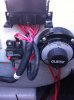
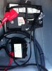
The 2nd Battery is a Dual Purpose battery and is connected to run all the boat electronics, while the original Starting Battery is reserved for guess what, starting... The principle is not to use the boat electronics to drain the starting battery. The switch that is supplied keeps the two batteries separated so you can use them individually. Should you have an emergency, you can combine the batteries for that emergency start - then switch back to independant mode.
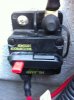
The ACR unit allows for both batteries to be charged from the altenator at the same time. It also has circutry that will separate the batteries if one falls below 12.4 volts so one bad battery cannot drain the good battery.
I bought a piece of white "starboard" (plastic plywood) and mounted everything to that.
Good luck.... Not too much of a pain to install, just keep your connections straight.
Marc
Attachments
joel.brayman
New Member
Marc,
Thanks a bunch. I will let you know how it goes...have a great weekend.
Joel
Thanks a bunch. I will let you know how it goes...have a great weekend.
Joel
rexsteiner
Active Member
Very Nice. i like these kinds of threads. Pictures and diagrams are worth a thousand words.
Cabanaboy07
New Member
Hey,
I am a real newbie at this and want to install a second battery in a 2012 Challenger SP. My goal is to make it as idiot proof as possible so sons with girlfriends don't end up on the other side of the lake with no juice to start....the boat that is. Do you have a step-by step account of what you did, and what parts you used? Is there a way to accomplish this without needing them to manually switch between batteries? Any guidance you can provide is much appreciated.
Cheers,
Joel
What I did in my Seadoo Speedster 07 was took in an empty spot in the engine compartment floor, I cut 2x4s to fit a battery box (also cut angle so it would be level) then took fiberglass mesh laid it on top of the 2x4s then painted fiberglass resin on top with several coats. After it dried I screwed down the battery box into the new fiberglassed 2x4s and installed a 29 group battery. Along with this I retrofitted the battery on-off switch to a 2 battery switch (Guest 2101). I hooked the OEM battery to the battery switch as battery 1, the new battery to battery 2, and everything drawing power to the 3rd post. always hook power drawing applications to this so when you turn the batteries off there is no worry of them draining. Also on the Guest 2101 switch i took a rotozip and drilled a hole on the side by the 3rd post so it would be easier to keep the wires separate. Depending on if you are installing a sound system, for the ground on the 2nd battery I grounded it to the existing batteries ground. But the sounds system (head unit & amp) ground itself, I grounded to the exhaust to avoid a ground loop (noise through stereo). For other questions ask I am happy to share my knowledge with wiring the stereo.
joel.brayman
New Member
Hey Marc,
Couple quick questions. In your diagram you show a black ground cable running from each battery, meeting and then going to the SI-ACR as a single cable. Am I joining the ground posts between the two batteries with a single cable and then running another longer single black ground cable from one of the two batteries to the SI-ACR relay and if so does it matter which battery the ground cable comes from?
I bought most of the items today, but did not get the fuse you show. I could only find Blue Sea dual fuses like the one you show. Are these fuses necessary? I assume they are placed on the battery and the cables run from the fuse? Also, you show an 20 Amp fuse and "Add-a Battery" diagram shows a 2 Amp fuse. Any thoughts about that? Sorry if my questions are rudimentary, just trying to make sure I have this figured out...appreciate the help.
Cheers,
Joel
Hey Marc,
Couple quick questions. In your diagram you show a black ground cable running from each battery, meeting and then going to the SI-ACR as a single cable. Am I joining the ground posts between the two batteries with a single cable and then running another longer single black ground cable from one of the two batteries to the SI-ACR relay and if so does it matter which battery the ground cable comes from?
I bought most of the items today, but did not get the fuse you show. I could only find Blue Sea dual fuses like the one you show. Are these fuses necessary? I assume they are placed on the battery and the cables run from the fuse? Also, you show an 20 Amp fuse and "Add-a Battery" diagram shows a 2 Amp fuse. Any thoughts about that? Sorry if my questions are rudimentary, just trying to make sure I have this figured out...appreciate the help.
Cheers,
Joel
Joel,
The Black Battery cable will run between the two batterries. The 16 awg black ground running to the ACR can connect to any battery. I put a small 10amp in-line fuse as they suggested. (missing from my diagram)
The fuses used from the positive terminals of each battery are 80amp in my diagram. I selected this from the Wire Size and Fuse ratings chart. My charging amps were roughly 60amps and I chose to use heavier #4 gauge battery cable. Each red battery post has an 80amp fuse and they ARE necessary. The 2amp fuse you are referring to is for the optional led.
Hope this helps you!
Marc
joel.brayman
New Member
Hey Marc,
I am looking for a bit more clarity and have some questions if you have the patience. I don't seem to have an attach file icon...I created a couple diagrams and have numbered the questions on the diagrams. It is a pdf file. I also have some pics of my current configuration and I think the location of some of the items (house breaker etc) are a bit different than yours so want to make sure I have this straight. I can send these through by email if you agree or if I have missed something and can attach the pdf let me know how...
Cheers,
Joel
Hey Marc,
I am looking for a bit more clarity and have some questions if you have the patience. I don't seem to have an attach file icon...I created a couple diagrams and have numbered the questions on the diagrams. It is a pdf file. I also have some pics of my current configuration and I think the location of some of the items (house breaker etc) are a bit different than yours so want to make sure I have this straight. I can send these through by email if you agree or if I have missed something and can attach the pdf let me know how...
Cheers,
Joel
Joel,
To attach files, move down on the page when you are posting text - to the attachment section to manage attachments and you can add them there. Let me know if you have an issue with this.
Marc
joel.brayman
New Member
A few more questions....
Hey Marc,
Went to the lake on the weekend but the weather was cold and wet so laid things out and came up with a couple more questions.
1) From your diagram-Is the red 16 awg running from the new battery to the LED connector on the SI-ACR a "new" cable?
2) From your diagram-Is the red 16 awg running from the SI connector to the starter solinoid new?
3) Can you ID the starter solinoid for me from my diagrams or photo's and if so where should I connect the 16 awg on it?
4) Diagram #1 - I assume this is what you called the house breaker?
4a) Do I connect all these wires to post 1 (top) in your diagram?
5) What is this and do I do anything with these wires?
6) Diagram#2 - What is this and do I do anything with these wires?
7) Not shown - I am going to run a new black 16 awg cable from the existing battery to the Ground connection on the SI-ACR?
8) I am going to place a new black 4 awg cable between the two batteries?
My configuration seems to be a bit different than yours and I am just trying to make sure I have all the parts and pieces identified correctly. I really appreciate your help...
cheers,
Joel
Attachments
Joel,
Please see attachment as well. Hope this helps.
1)From your diagram-Is the red 16 awg running from the new battery to the LED connector on the SI-ACR a "new" cable?
- This is an optional LED that will tell you the batteries are combined. I installed it by the rear seat so I can see it while running. It is not necessary since there is an LED on the ACR unit itself. The connection can be made to any battery since the only time you will see this LED on, is when both batteries are above a certain voltage (I believe 12.4 volts). Once either battery drops below that level, the ACR will separate them until they are being recharged.
2) From your diagram-Is the red 16 awg running from the SI connector to the starter solenoid new?
- Yes
3) Can you ID the starter solenoid for me from my diagrams or photo's and if so where should I connect the 16 awg on it?
- See attached pictures
4) Diagram #1 - I assume this is what you called the house breaker?
- #5 on your diagram would be the house breaker
4a) Do I connect all these wires to post 1 (top) in your diagram?
- The idea is connecting the battery cable from your starter solenoid to one post (#2) and your main breaker (house) to post #1 – this way they use separate batteries.
5) What is this and do I do anything with these wires?
6) Diagram#2 - What is this and do I do anything with these wires?
- This is the Starter Solenoid
7) Not shown - I am going to run a new black 16 awg cable from the existing battery to the Ground connection on the SI-ACR?
- Either battery is fine
8) I am going to place a new black 4 awg cable between the two batteries? \
- Yes
Attachments
joel.brayman
New Member
Marc,
Fantastic and thanks for all the details. Headed to the lake this weekend and will get this job done. One last question. In my diagram #1 there is a group of wires coming from #4 which I labelled #4a. In your diagram top post 1 on the new switch goes to the house breaker while bottom post 1 goes to the new battery. Do you know what I do with the group of wires labelled 4a? I have traced everything else based on your info and feel comfortable, this is the last connection I am curious about.
Thanks for all your help it is very much appreciated. I plan to tackle sound proofing next and promise I wont have as many, if any questions! Have a great day.
Cheers,
Joel
Marc,
Fantastic and thanks for all the details. Headed to the lake this weekend and will get this job done. One last question. In my diagram #1 there is a group of wires coming from #4 which I labelled #4a. In your diagram top post 1 on the new switch goes to the house breaker while bottom post 1 goes to the new battery. Do you know what I do with the group of wires labelled 4a? I have traced everything else based on your info and feel comfortable, this is the last connection I am curious about.
Thanks for all your help it is very much appreciated. I plan to tackle sound proofing next and promise I wont have as many, if any questions! Have a great day.
Cheers,
Joel
Joel,
I'm not certain if this is part of the "house" circuits, but I can tell you that the starter cable should go to your #2 top post and these group of cables should probably go to the #1 post. See if you can identify them by doing some tracing. I would have thought these wires start at the fusebox.
Good luck this weekend!
Marc
- Status
- Not open for further replies.
Similar threads
- Replies
- 23
- Views
- 1,976
- Replies
- 2
- Views
- 811
- Replies
- 0
- Views
- 457