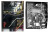
I am a dentist so I have a self heating hobby knife so that will be no problem. Oh and the x-Ray was taken with my cephalometric x-Ray machine. Anyone for braces on their seadoo?
That is a great plan. I have already ordered the diode and potting resin. Thank you so much for the detailed plan.
Btw I have temporarily replaced the MPEM with a used one but the beep when attaching the key is barely audible. Is there a fix for that?
You've got the MPEM repair nailed at this point, the only thing you may want to consider if it happens again using black automotive RTV to seal it up is an easier alternative for removal versus potting compound after the fact (god forbid) the need arise to revisit the project.
So your beeper issue, was this not a problem with the original module and began with it's current replacement or just been a weak tone all along?
I need to review some service records for total numbers and I'll update this post with some more info, I have found this module in particular to have an issue after repairing the diode and I'll grab a data screenshot so you can see what I'm referring to.
On Edit:
There's been a total of eleven of these one year production 1997 GTX modules on my bench since I started a different record keeping process that captures internal data screenshots of the readable/writable programming functions of these modules.
Of those, five of them had lost the accessory power cutoff duration programming function and had simply reset themselves to a zero value when the diode was taken out.
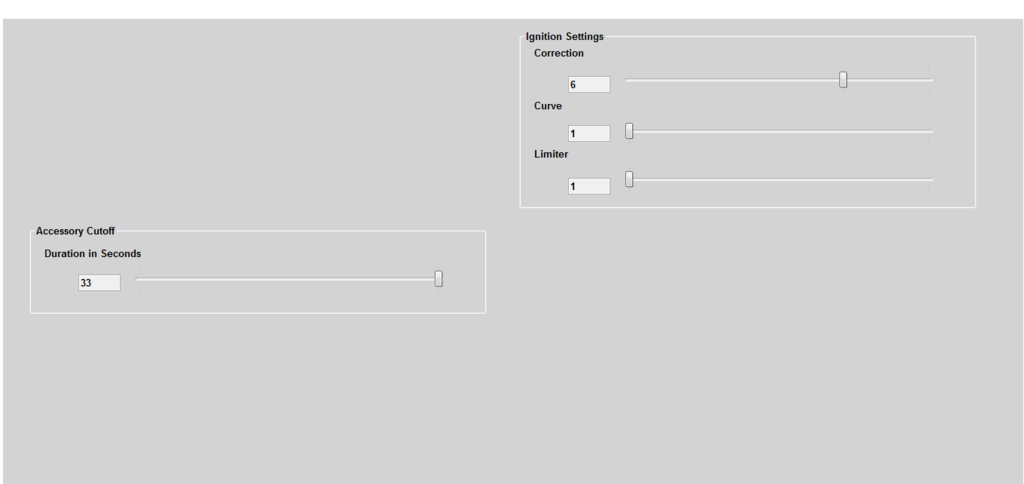
Not a big deal, the fix is a simple swipe with the cursor to reset the value back to a maximum duration of 33 seconds but running the module without the programming value reset will result in it never shutting off power to the dash creating a constant battery draw and the ROM partition of the memory that stores total engine time running hours and minutes will tick away forever more.
If you notice your dash doesn't go to sleep after 30 seconds or so just shoot me a message you can ship that over and I'll reset the programming value for you.
There are three relevant data display screens in your module, this is the one displaying the duration cutoff programming and ignition timing correction value.