• This site contains eBay affiliate links for which Sea-Doo Forum may be compensated.

1997 gsi (720) stator

Status
Not open for further replies.

s91wff

New Member
I had to change the stator generator magneto. i did this because the ski died on me on the water brought it home and ohm tested it and go no readings what so ever. now that i have done so, when i hook battery up it seems to be sending power back to stator and trying to turn the flywheel. does anyone have any thoughts on this.

thanks!
 
Sounds like your rectifier is shorted, and perhaps even the protective fuse is too large. Be careful not to burn up the new stator windings, the fuse capacity is limited to keep this from happening.

Does this ski use the full wave bridge rectifier that's about 1.25" square? It would have two yellow wires, a red and possibly a black wire for ground. You can test this one using a DVOM on ohms scale and they're dirt cheap, even Radio Shack used to carry a similar bridge rectifier.

https://en.wikipedia.org/wiki/Diode_bridge
 
Last edited by a moderator:
Yes that is the exact rectifier. I have replaced it with a new one and still have the same issue. It is also blowing the 15 amp fuse in rear electric box when I hook battery up. If I disconnect the stator wiring harness The fuse does not blow. Ohm readings on stator and generating coil are all still within specs so that is still good!
 
Okay got ya. The reason the engine is turning slightly is b/c DC current from your battery is flowing through the stator windings. This should not happen. The rectifier only passes current from the stator to the battery in one direction, the rectifier blocks current from the battery into the stator.

So either your rectifier is shorted, mislabeled or connected incorrectly. The "+" terminal of rectifier connects to battery +, "-" of rectifier connects to ground, and both "~" are AC input from stator winding.

There are 4 diodes inside the rectifier bridge, you can test all 4 of them using an ohmmeter to make sure each one flows current in only one direction.
 
So far I understand all that and get it. The rectifier I got has the blk,red,&2!yellows. The only difference is the original part had a yellow and yellow,blk. The place where I got it from said it makes no difference where I put the 2 yellow wires. What is the procedure for testing the rectifier?
 
Another test you can use is disconnect the stator and with the battery connected normally then using a trailer test light (small 12V tail light bulb inside a handle) connect test light ground wire to battery "-" terminal and connect test probe of light to either or both yellow wires of rectifier. The test light should not be lit. If the test light does lite this means current from your battery is flowing backwards through your rectifier.
 
Ok so both new and old rectifier have power on one of the yellow wires. The old unit shows power on the yellow wire and the new shows power on the what would be yellow/blk wire.
 
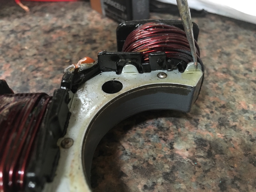
Okay, what's the part number on the original rectifier, I want to confirm I'm taking you down the right path (4 diode bridge rectifier)

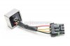
I think I found it, it seems to be the simple bridge rectifier. Looks like it mounts to the MPEM using a bolt.

278001056 RECTIFIER ASS'Y

Does the mounting boss of the MPEM seem to have an electrical connection using the mounting bolt or is the mechanical mounting essentially just plastic? If just plastic then this looks like simple 4-diode bridge rectifier.

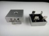
There are 30Amp 1000PIV 4-diode bridges with terminal lugs (without the fancy Seadoo connector) listed on ebay for under $3, KBPC3010 is an example.

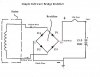
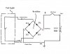
The stator makes AC current and this is fed to the rectifier for conversion to DC current to charge the battery. This is the simplest of Seadoo's charging systems, and there is no voltage regulation in this particular design except the stator itself is designed not to overcharge the battery.

In this drawing, you can see if Diode D1 is shorted (conducts in both directions) there will be battery voltage on the yellow stator wire. But diode D2 must also be shorted to allow battery current to flow back to ground through the stator. Same thing would be true for diodes D3 and D4.

So there must be at least two shorted diodes for battery current to flow backwards to ground through the rectifier and stator.
 

Attachments

  • s-l400.jpg
    s-l400.jpg
    9.8 KB · Views: 16
  • Seadoo 1997 GSI Rectifier.jpg
    Seadoo 1997 GSI Rectifier.jpg
    44.3 KB · Views: 14
  • s-l400.jpg
    s-l400.jpg
    12.4 KB · Views: 13
Last edited by a moderator:
I will have to order a new one and try it. Only 1 yellow wire was lighting up with tester. I will get new and try it. Thanks
 
I have one more test for you, connect the two leads of the test light to the two yellow wires of the rectifier. IF the light is lit, this confirms current is flowing in reverse through both sides of the rectifier bridge.

The 1st test above only confirms current is flowing in reverse through one side of the bridge (not good, assuming I understand this particular circuit, disclaimer: sometimes my assumptions are incorrect).

But in order for current to flow in reverse through the stator (and possibly burn it up if fuse is too large capacity) while engine is off, current must flow in reverse through both sides of the rectifier.

Thus, connecting the test light in place of the stator will confirm if current was flowing in reverse through the stator (rectifier problem).
 
Ok, I don't think test light will work for that test. I did however use a volt meter on a ground and each one of the yellow wires and there is 12v at the rectifier. I then moved to the plug for the stator and tested both yellow wires and confirmed 12v in both. I get the same reading out of both rectifiers the original and the one I was going to change it with. I have another one coming. Was it possible to get a bum unit? Or did it blow do to something else?

Are the ground wires attached (3) of them to the ignition coil supposed to have a ground at all times, or only when the coil gets activated? I ask because the black wire coming out of the rear electric box is not grounded (must be broken in harness.) thoughts?
 
Here's how to connect a test light. The reason I suggest a light is this tells you both voltage and current are present while a voltmeter only measures voltage. Measuring voltage is the preferred method in some cases when precision is required.

A voltmeter can be connected in the same way but we don't get the benefit of knowing there's current.

I don't have the schematic for your particular ski. However, it can be found in the factory service manual usually a free download PDF file. I encourage you to download the manual and I think you can follow the wiring diagram to answer your grounding question plus there's boatloads of other important info.

Anyway, if the ground wires you're referring to are black, I think it's safe to assume they're grounded all the time. Usually they go straight to the battery negative terminal, assuming it's like the other Seadoo skis. That e-box ground is also for the starter solenoid ground and without it the starter solenoid won't operate thus no starter. Starter solenoid is energized by the MPEM through the Yellow wire with Red stripe (Y/R is the standard solenoid wire color for marine wiring). I'm guessing it probably seems like there's no ground there due to minor corrosion or shellac/paint coating is insulating the metal surface making connection with meter probe difficult?
 

Attachments

  • Seadoo 1997 GSI Rectifier2.jpg
    Seadoo 1997 GSI Rectifier2.jpg
    39.3 KB · Views: 8
Was it possible to get a bum unit? Or did it blow do to something else?

It's possible I suppose, if you believe a 12 year old Chinese factory worker might make a mistake near the end of his 18 hour shift, or someone returned a dud they blew up and the seller shipped it to you.

This is kind of why I'd like to test further, using your ohmmeter. I have to guess a little at what's exactly in the black box but it should be 4 diodes connected in a bridge. Diodes only conduct current in one direction unless they're damaged. In the direction of the arrow. The electrical equivalent of a one-way check valve.

We can wait for the new one, but there's no explanation for why the previous two failed..... Or why the original stator failed or how it measured. Plenty of mystery exists. :)
 
Well we got it! 2 bad rectifiers and the stator was not built properly. There was a piece of isolation plastic missing. That's was make the short and blowing the fuse. Oh yeah that was on the bottom side of the coil. So I guess you were right about the 12yo at the end of an 18 day!!!!! 1st photo is missing 2nd is the opposite side in tact.
72.jpg
73.jpg
 
Last edited by a moderator:
Status
Not open for further replies.
Back
Top